
New energy combined power bank

A combined charging treasure technology, applied in circuits, current collectors, electric vehicles, etc., can solve problems such as aging of internal electronic components, reduce battery performance, increase fire and explosion, etc., to increase explosion-proof strength and drop resistance , Increase the effect of structural strength

Pending Publication Date: 2021-11-09
张晓娟
View PDF0 Cites 2 Cited by
  • Summary
  • Abstract
  • Description
  • Claims
  • Application Information

AI Technical Summary

Problems solved by technology

There are already some mobile power supplies on the market whose internal battery heat cannot be effectively discharged during charging, resulting in aging of the internal electronic components, increasing the risk of fire and explosion, and reducing the performance of the battery. The mobile power supply is only protected against explosion through the shell. The explosion-proof effect is poor, and a single battery module is used inside the power bank. Generally, the battery has a large capacity and needs to be replaced as a whole once it is damaged. The cost is high, and the existing power bank adopts a fully enclosed structure, which is not convenient for internal maintenance.

Method used


Image

  • New energy combined power bank
  • New energy combined power bank
  • New energy combined power bank

Examples


Embodiment Construction

[0027] Below, in conjunction with accompanying drawing and specific embodiment, the present invention is further described:

[0028] In the description of the present invention, it should be noted that the terms "top", "bottom", "one side", "another side", "front", "rear", "middle part", "inner", " The orientation or positional relationship indicated by "top", "bottom", etc. is based on the orientation or positional relationship shown in the drawings, which is only for the convenience of describing the present invention and simplifying the description, rather than indicating or implying that the referred device or element must have specific orientation, construction and operation in a specific orientation, and therefore should not be construed as limiting the invention; the terms "first", "second" and "third" are used for descriptive purposes only and should not be construed as indicating or implying relative Importance; In addition, unless otherwise clearly stipulated and lim...


PUM


Abstract

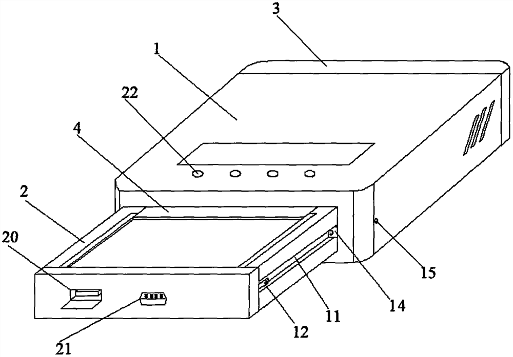
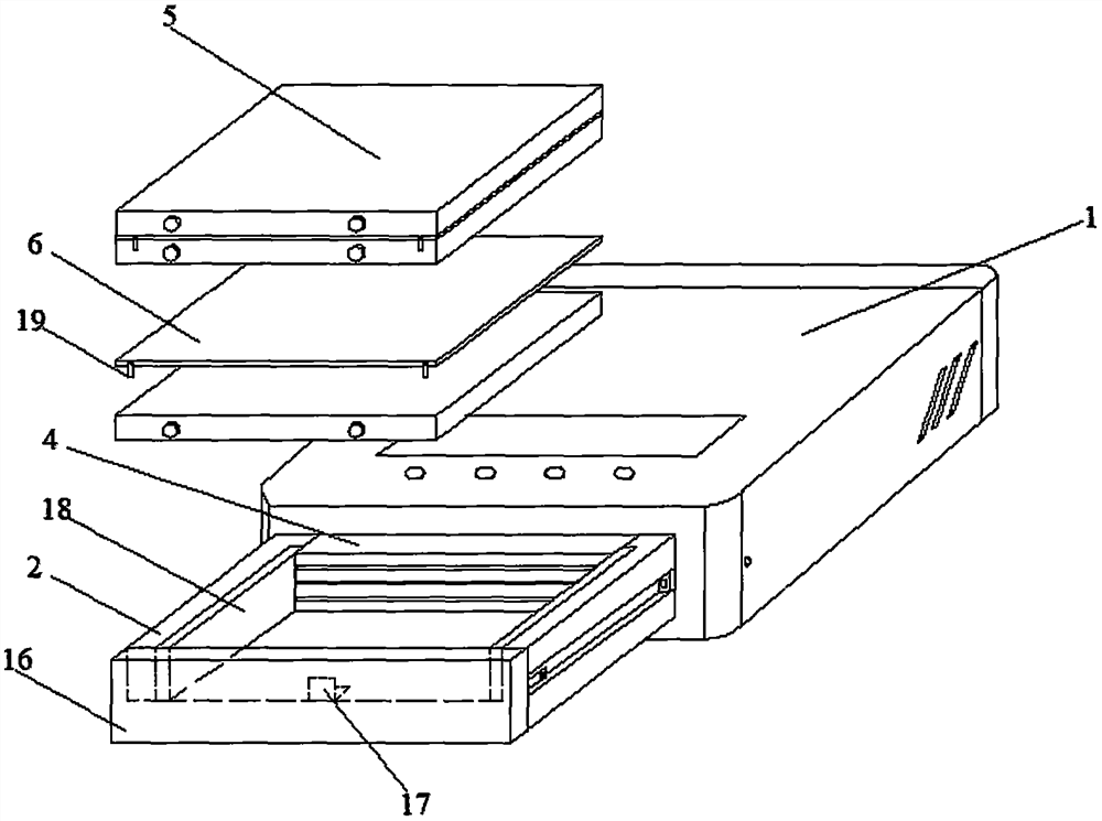
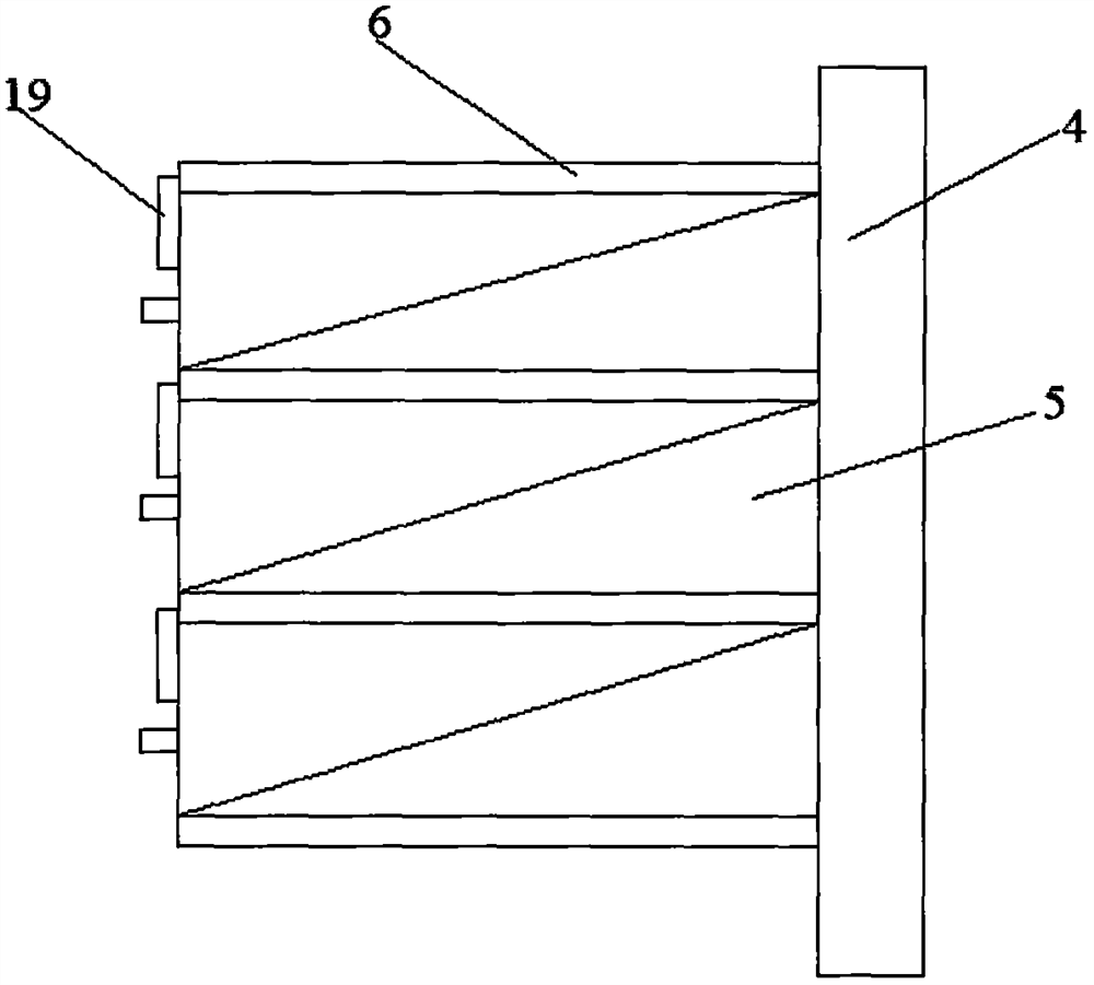
The invention discloses a new energy combined power bank which comprises a main body, a loading box, a rear end cover, a heat dissipation plate, partition pieces, a battery, fans, temperature sensing elements, a clamping column, a sliding table and a spring. The sliding table is fixed to the two side walls of an inner cavity of the main body. A sliding groove is formed in the side wall of the loading box, the heat dissipation plate is fixed to the rear end of the loading box, and the partition pieces are fixed to the heat dissipation plate. The battery is arranged between the partition pieces. A pressing piece is installed at the front end of each partition piece, each partition piece is composed of a metal heat absorption plate and heat conduction glue, and the temperature sensing elements are arranged on the metal heat absorption plates. The plurality of evenly-distributed fans are installed on the inner side of the rear end cover. An opening and closing plate is installed at the front end of the loading box through a hinge piece, and a charging and discharging plate is installed on the inner side of the opening and closing plate. The clamping column is fixed in the end, close to the opening and closing plate, of the sliding groove, and an elastic buckle is installed on the clamping column. An opening is formed in the sliding table, and an elastic buckle hole is formed in the side face of the sliding table. A needle hole is formed in one side of the front end of the main body and communicated with the elastic buckle hole. The new energy combined power bank is good in explosion-proof performance, convenient to overhaul, low in maintenance cost and long in service life.

Description

technical field [0001] The invention relates to the technical field of mobile power supplies, in particular to a new energy combined charging treasure. Background technique [0002] Power Bank is a portable charger that integrates power supply and charging functions. It generally uses a lithium battery as a power storage unit, which is convenient and quick to use, and can charge digital devices such as mobile phones and tablet computers anytime and anywhere. [0003] With the development of charging treasure mobile power, users are not only satisfied with being able to charge, but more users are pursuing safety and service life. There are already some mobile power supplies on the market whose internal battery heat cannot be effectively discharged during charging, causing the internal electronic components to age, increasing the risk of fire and explosion, and reducing the performance of the battery. The mobile power supply is only protected against explosion through the she...

Claims


Application Information

Patent Timeline
IPC IPC(8): H02J7/00H01M10/613H01M10/623H01M10/6554H01M10/6556H01M10/6563H01M50/204H01M50/242H01M50/244H01M50/247
CPCH02J7/0044H02J7/00309H02J7/0068H01M10/613H01M10/623H01M10/6554H01M10/6556H01M10/6563H01M50/204H01M50/242H01M50/244H01M50/247Y02E60/10
Inventor 张晓娟
Owner 张晓娟
Learn More