Plate punching machine feeder and feeding method thereof

A technology of sheet punching and feeding machine, applied in the field of sheet metal processing, can solve the problems of easily crushing the conveyor belt, reducing production efficiency, uneven quality, etc., to avoid potential safety hazards, improve the degree of automation, and reduce the effect of intervention

Pending Publication Date: 2021-11-12
邓彩霞
View PDF11 Cites 1 Cited by
  • Summary
  • Abstract
  • Description
  • Claims
  • Application Information

AI Technical Summary

Problems solved by technology

[0003] At present, most ordinary punching machines are almost all manually operated, manual feeding, low efficiency, uneven quality, and manual feeding and stamping are very dangerous. Work-related accidents occur frequently, and the personal safety of workers cannot be guaranteed. Although there are a small number of punching machines The factory uses an automatic feeding machine, but this part of the automatic feeding machine has poor flexibility and a single action, which is suitable for occasions where the mold does not need to be replaced frequently, the product variety is single, and mass production; while modern production tends to produce small batches of products with multiple varieties production mode, and the traditional manual feeding requires a conveyor belt to transfer the sheet to the vicinity of the punching machine and then manually feed the material, which cannot be continuously mechanized production and reduces production efficiency. Moreover, due to the huge instantaneous pressure of the punching machine during work, manual feeding is very dangerous. Metal processing Due to the heavy weight of the metal sheet, it is easy to crush the conveyor belt, and the staff who feed the material are very tired, which increases the production cost

Method used


Image

  • Plate punching machine feeder and feeding method thereof
  • Plate punching machine feeder and feeding method thereof
  • Plate punching machine feeder and feeding method thereof

Examples


Embodiment Construction

[0030] The following will clearly and completely describe the technical solutions in the embodiments of the present invention with reference to the accompanying drawings in the embodiments of the present invention. Obviously, the described embodiments are only some, not all, embodiments of the present invention. Based on the embodiments of the present invention, all other embodiments obtained by persons of ordinary skill in the art without making creative efforts belong to the protection scope of the present invention.

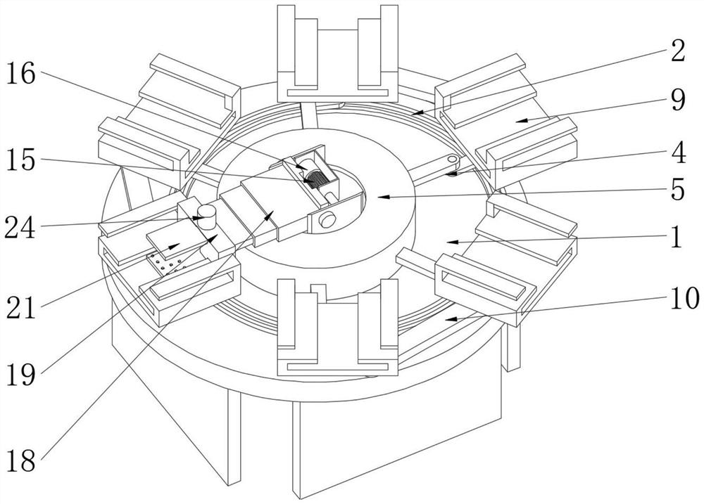
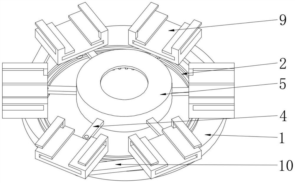
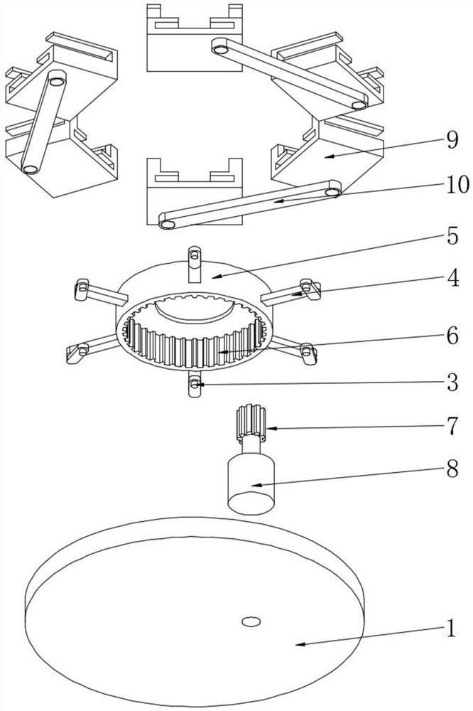
[0031] see Figure 1-9, a plate punch feeder, including a support plate 1, by setting the support plate 1 as a circular tray, the circular device is conducive to the cycle of loading and unloading of the device, and on the upper part of the support plate 1 through the rotating track 2, The rotating block 3, the swing rod 4 and the rotating table 5 are movably equipped with a feeding plate 9, which is convenient for maintaining the direction of the feeding plat...


PUM


Abstract

The invention relates to the technical field of plate machining, and discloses a plate punching machine feeder. The feeder comprises a supporting plate, a rotating rail is fixedly installed on the upper portion of the supporting plate, a rotating block is movably installed in the rotating rail, and the upper end of the rotating block is fixedly installed at the bottom of one end of a swing rod. The other end of the swing rod is fixedly connected to a rotating table, the bottom of the rotating table is movably installed in the middle of the upper portion of the supporting plate, and a gear groove is formed in the rotating table. According to the plate punching machine feeder and the feeding method thereof, the supporting plate is arranged as a circular tray, circular feeding and discharging of the device are facilitated through the circular tray; and because the feeding plate is movably installed on the upper portion of the supporting plate through the rotating rail, the rotating block, the swing rod and the rotating table, the direction of the feeding plate on the upper portion of the supporting plate can be conveniently and regularly adjusted when the device rotates, and a plate on the upper portion of the feeding plate can be conveniently punched.

Description

technical field [0001] The invention relates to the technical field of sheet metal processing, in particular to a sheet metal punch feeder and a feeding method thereof. Background technique [0002] Punching machine is a kind of stamping press. In mechanical processing production, stamping process is a relatively traditional mechanical processing method. The punching process has the characteristics of saving material energy and high efficiency, and the stamping process does not require high technical requirements for operators. , the punch press can process products that cannot be processed by other mechanical equipment through the application of various molds, so its use is becoming more and more extensive. At present, most of the punch presses are fed manually. [0003] At present, most ordinary punching machines are almost all manually operated, manual feeding, low efficiency, uneven quality, and manual feeding and stamping are very dangerous. Work-related accidents occur...

Claims


Application Information

Patent Timeline
Patent Type & Authority Applications(China)
IPC IPC(8): B21D43/14B21D43/20B21D43/24B21D43/11B21D43/02
CPCB21D43/14B21D43/20B21D43/24B21D43/11B21D43/026
Inventor 邓彩霞
Owner 邓彩霞
Why Eureka
Try Eureka