Prefabricated concrete ground beam-frame column connecting joint and construction method thereof

A prefabricated concrete, connecting node technology, applied in the direction of structural elements, building components, building reinforcements, etc., can solve the problems of lack of fast and efficient detection methods, insufficient tensile and shear resistance, and narrow sleeve operating space. Improve assembly efficiency and connection quality, avoid premature cracking, and reduce labor costs

Pending Publication Date: 2021-11-12
CHANGAN UNIV
View PDF0 Cites 0 Cited by
  • Summary
  • Abstract
  • Description
  • Claims
  • Application Information

AI Technical Summary

Problems solved by technology

The sleeve connection has defects such as leakage irrigation, insufficient irrigation, and insufficient insertion depth of steel bars in the project. There is no fast and efficient detection method, and it is difficult to guarantee the force transmission of steel bars. The quantity is large, the operation space of the sleeve is narrow, and it is extremely difficult to align the steel bars with holes during on-site assembly, resulting in low construction efficiency
The contact surface between the secondary poured concrete and the prefabricated components is prone to cracking, and the tensile and shear resistance is insufficient, so it cannot take advantage of the fast and efficient characteristics of the prefabricated structure

Method used


Image

  • Prefabricated concrete ground beam-frame column connecting joint and construction method thereof
  • Prefabricated concrete ground beam-frame column connecting joint and construction method thereof
  • Prefabricated concrete ground beam-frame column connecting joint and construction method thereof

Examples


Embodiment Construction

[0028] The present invention is described in further detail below in conjunction with accompanying drawing:

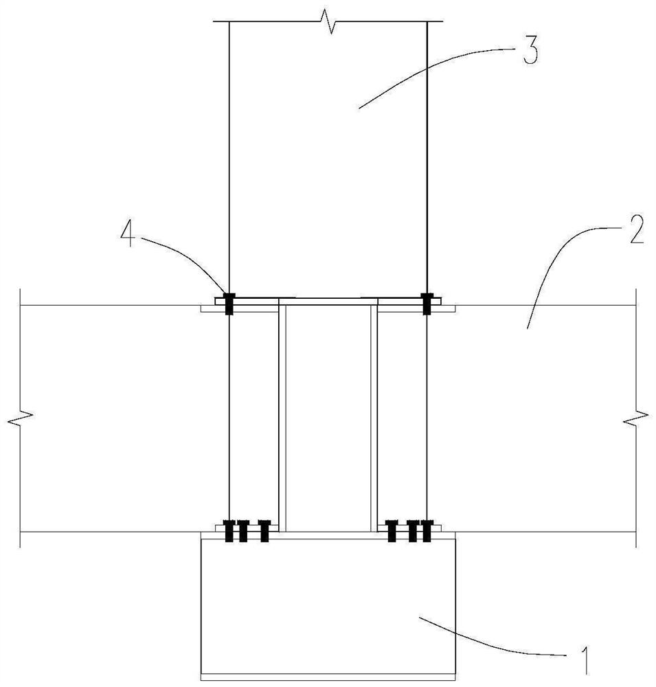
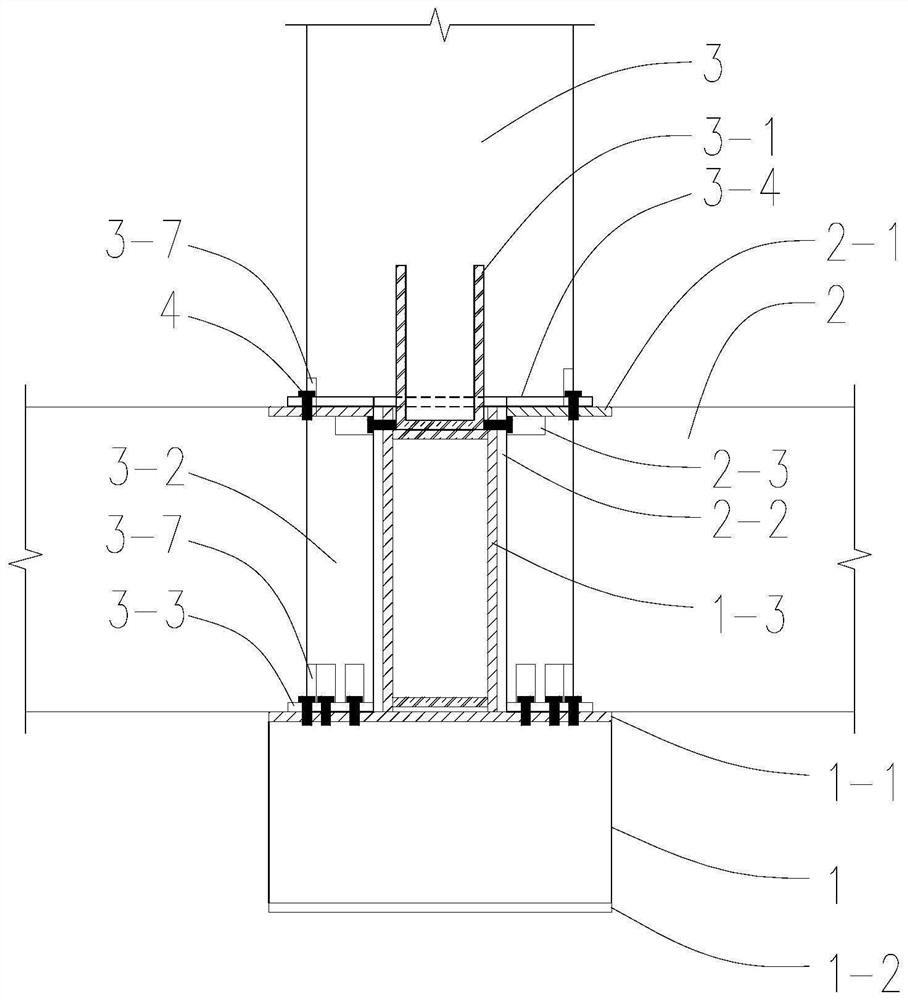
[0029] Such as figure 1 As shown, it is the prefabricated concrete ground beam-frame column connection node according to the present invention, which includes the conversion column 1, the ground beam 2 and the frame column 3 which are sequentially connected from bottom to top.

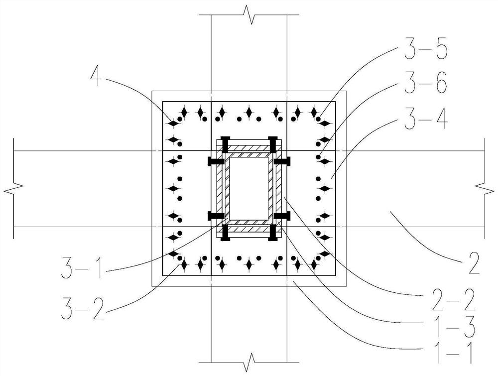
[0030] The number of ground beams 2 is two to four, depending on the top view, the ground beams 2 are connected to the core column 13 in a straight, L-shaped, T-shaped or cross-shaped. In this embodiment, a cross is taken as an example.

[0031] The top steel plate 11 and the bottom steel plate 12 with bolt holes are pre-embedded at the bottom and top of the concrete conversion column 1. There is a core column 13 made of high-strength steel. The core column 13 is made of rectangular steel pipes. Bolt holes are provided on the four wall panels. The height of the core column is the same as that...


PUM


Abstract

The invention discloses a prefabricated concrete ground beam-frame column connecting joint and a construction method thereof. The prefabricated concrete ground beam-frame column connecting joint comprises a conversion column, a ground beam and a frame column which are sequentially connected from bottom to top. A top surface steel plate and a core column are arranged on the top surface of the conversion column, the core column is internally hollow, and the height of the core column is equal to that of the ground beam; an end steel plate and a top steel plate are correspondingly arranged on the end face and the top face of the ground beam, and the end steel plate is connected with the side face of the core column through bolts; corner limbs and bottom steel plates are arranged on the bottom surfaces of the frame columns; the corner limbs extend out of the bottom surface of the frame column to the top steel plate of the conversion column, bottom steel plates are arranged at the bottoms of the corner limbs, the bottom steel plates and the top steel plate are connected through bolts, the corner limbs are located at included angles formed among the ground beams, the side faces of the corner limbs make contact with the ground beam, and the extending length of the corner limbs is equal to the height of the ground beams; and the bottom steel plates are arranged away from the corner limbs, the sum of vertical projection areas of the corner limbs and the bottom steel plates is equal to the sectional area of the frame column, and the bottom steel plates are connected with the top steel plate of the ground beam through bolts.

Description

technical field [0001] The invention belongs to the field of civil engineering and prefabricated assembled structures, and relates to a prefabricated concrete ground beam-frame column connection node and a construction method thereof. Background technique [0002] The connection nodes and construction methods of prefabricated components are the key issues of prefabricated structures, especially the connection nodes of precast concrete ground beams and frame columns, which have a great influence on the green low-carbon assembly construction and the overall mechanical performance of the structure. [0003] The existing precast concrete ground beams and frame columns mostly use reserved steel bars, which are connected by grouting sleeves and then concrete is poured twice to complete the on-site assembly connection. interface to work together. The sleeve connection has defects such as leakage irrigation, insufficient irrigation, and insufficient insertion depth of steel bars in...

Claims


Application Information

Patent Timeline
Patent Type & Authority Applications(China)
IPC IPC(8): E04B1/58E04B1/20E04B1/21E04B1/30E04C5/03
CPCE04B1/58E04B1/20E04B1/21E04B1/215E04B1/30E04C5/03E04B2001/5887
Inventor 段留省
Owner CHANGAN UNIV
Why Eureka
Try Eureka