
Subgrade compaction uniformity calculation method, device, equipment and readable storage medium

A calculation method and uniformity technology, applied in the field of calculation method, device, equipment and readable storage medium of subgrade compaction uniformity, can solve the problem of no detection method, etc., and achieve the effect of reducing errors

Active Publication Date: 2022-01-07
SOUTHWEST JIAOTONG UNIV
View PDF0 Cites 0 Cited by
  • Summary
  • Abstract
  • Description
  • Claims
  • Application Information

AI Technical Summary

Problems solved by technology

[0002] At present, there is no clear detection technology for the uniformity of subgrade compaction (filling). The existing detection is based on the elevation to judge. In fact, whether the subgrade is uniform or not should be related to the packing density and seasoning inside the subgrade. It is related to the distribution of materials, and the evaluation from the elevation alone can only show that there are relatively large limitations. The "Code for Design of Highway Cement Concrete Pavement" requires that "the subgrade should be stable, dense, and homogeneous, and provide uniform support for the pavement structure", " The Code for Design of Highway Asphalt Pavement requires that "the subgrade must be dense, uniform and stable", but there are no specific relevant detection methods, so there are still relatively large defects in the detection of subgrade compaction uniformity

Method used


Image

  • Subgrade compaction uniformity calculation method, device, equipment and readable storage medium
  • Subgrade compaction uniformity calculation method, device, equipment and readable storage medium
  • Subgrade compaction uniformity calculation method, device, equipment and readable storage medium

Examples


Embodiment 1

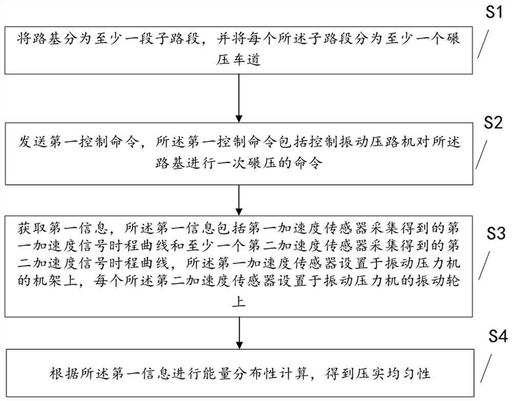
[0057] This embodiment provides a method for calculating the uniformity of subgrade compaction.

[0058] see figure 1 , the figure shows that the method includes step S100, step S200, step S300 and step S400.

[0059] S100. Divide the subgrade into at least one subsection, and divide each subsection into at least one rolling lane.

[0060] It can be understood that, in this step, the method of dividing the roadbed into multi-value road sections is to divide the roadbed with a preset length, and in this method, it is recommended to divide a sub-road section with 200m as the standard. For those skilled in the art, the sub-sections can be divided according to actual needs, and it can also be understood that the more sub-sections are divided, the higher the calculation accuracy of the uniformity is.

[0061] At the same time, it should be noted that for different roadbeds, the rolling range of the vibratory roller is limited, so the rolling lanes that can be divided into each su...

Embodiment 2

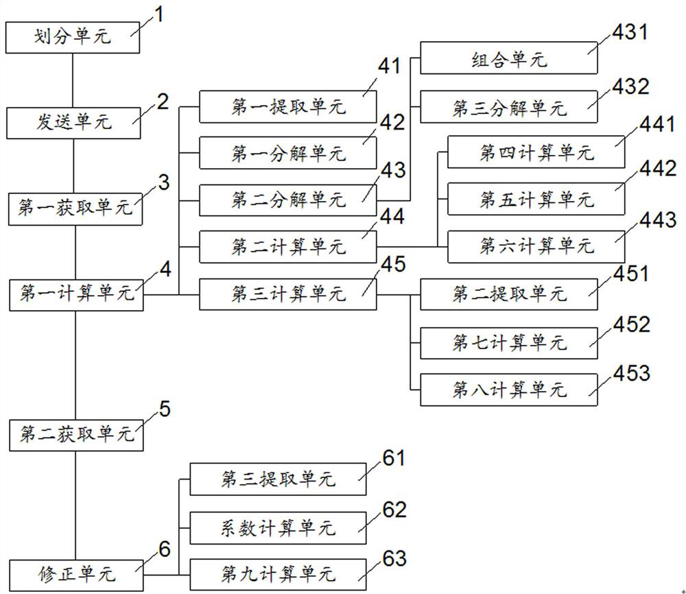
[0118] Such as image 3 As shown, this embodiment provides a roadbed compaction uniformity calculation device, the device includes:

[0119] The dividing unit 1 is used for dividing the roadbed into at least one subsection, and dividing each subsection into at least one rolling lane.

[0120] The sending unit 2 is configured to send a first control command, where the first control command includes a command to control the vibratory road roller to roll the roadbed once.

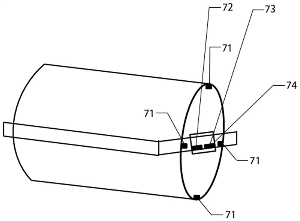
[0121] The first acquisition unit 3 is configured to acquire first information, the first information includes a first acceleration signal time history curve acquired by the first acceleration sensor 72 and a second acceleration signal time history curve acquired by at least one second acceleration sensor 71 , the first acceleration sensor 72 is arranged on the frame 74 of the vibration press, and each second acceleration sensor 71 is arranged on the vibration wheel of the vibration press.

[0122] The first...

Embodiment 3

[0149] Corresponding to the above method embodiment, this embodiment also provides a roadbed compaction uniformity computing device, a roadbed compaction uniformity computing device described below and a roadbed compaction uniformity computing device described above The methods can be referred to each other.

[0150] Figure 4 It is a block diagram of a roadbed compaction uniformity computing device 800 shown according to an exemplary embodiment. Such as Figure 4 As shown, the roadbed compaction uniformity computing device 800 may include: a processor 801 and a memory 802 . The roadbed compaction uniformity computing device 800 may also include one or more of a multimedia component 803 , an I / O interface 804 , and a communication component 805 .

[0151]Wherein, the processor 801 is used to control the overall operation of the roadbed compaction uniformity calculation device 800, so as to complete all or part of the steps in the above-mentioned roadbed compaction uniformit...


PUM


Abstract

The present invention provides a roadbed compaction uniformity calculation method, device, equipment and readable storage medium, which relate to the technical field of roadbed compaction, including dividing the roadbed into at least one subsection, and dividing each subsection into at least one roller section. Rolling the roadway; sending the first control command, the first control command includes an order to control the vibratory roller to roll the roadbed once; obtaining the first information, the first information includes the time history curve of the first acceleration signal collected by the first acceleration sensor and The time history curve of the second acceleration signal collected by at least one second acceleration sensor; the energy distribution calculation is performed according to the first information to obtain the compaction uniformity, and the present invention obtains the subgrade by processing the collected dynamic signal on the vibratory roller The uniformity coefficient, the whole process does not need to measure the height manually, reducing the error caused by human operation.

Description

technical field [0001] The present invention relates to the technical field of roadbed compaction, in particular to a calculation method, device, equipment and readable storage medium for roadbed compaction uniformity. Background technique [0002] At present, there is no clear detection technology for the uniformity of subgrade compaction (filling). The existing detection is based on the elevation to judge. In fact, whether the subgrade is uniform or not should be related to the packing density and seasoning inside the subgrade. It is related to the distribution of materials, and the evaluation from the elevation alone can only show that there are relatively large limitations. The "Code for Design of Highway Cement Concrete Pavement" requires that "the subgrade should be stable, dense, and homogeneous, and provide uniform support for the pavement structure", " The Code for Design of Highway Asphalt Pavement requires that "the subgrade must be dense, uniform and stable", but...

Claims


Application Information

Patent Timeline
Patent Type & Authority Patents(China)
IPC IPC(8): G06F17/11E01C19/28
CPCG06F17/11E01C19/28
Inventor 连静杨长卫童心豪张良陈桂龙
Owner SOUTHWEST JIAOTONG UNIV
Learn More