Deep foundation pit bottom plate concrete pouring system with multiple supporting beams and construction method thereof

A deep foundation pit and multi-support technology, applied in infrastructure engineering, construction, etc., can solve the problems of poor pouring quality, unfavorable traffic, and low pouring efficiency, so as to save later maintenance costs and reduce the possibility of cracks and water leakage , to overcome the adverse effects of traffic

Pending Publication Date: 2021-11-16
CHINA CONSTR EIGHT ENG DIV CORP LTD
View PDF7 Cites 0 Cited by
  • Summary
  • Abstract
  • Description
  • Claims
  • Application Information

AI Technical Summary

Problems solved by technology

[0004] In order to solve the above problems, the present invention provides a deep foundation pit floor concrete pouring system with multiple support beams and a construction method thereof. The concrete pouring system uses multiple support beams as support points, which reduces the occupation of the construction site and overcomes the Unfavorable traffic, low pouring efficiency and substandard pouring quality caused by the narrow construction site

Method used


Image

  • Deep foundation pit bottom plate concrete pouring system with multiple supporting beams and construction method thereof
  • Deep foundation pit bottom plate concrete pouring system with multiple supporting beams and construction method thereof
  • Deep foundation pit bottom plate concrete pouring system with multiple supporting beams and construction method thereof

Examples


Embodiment Construction

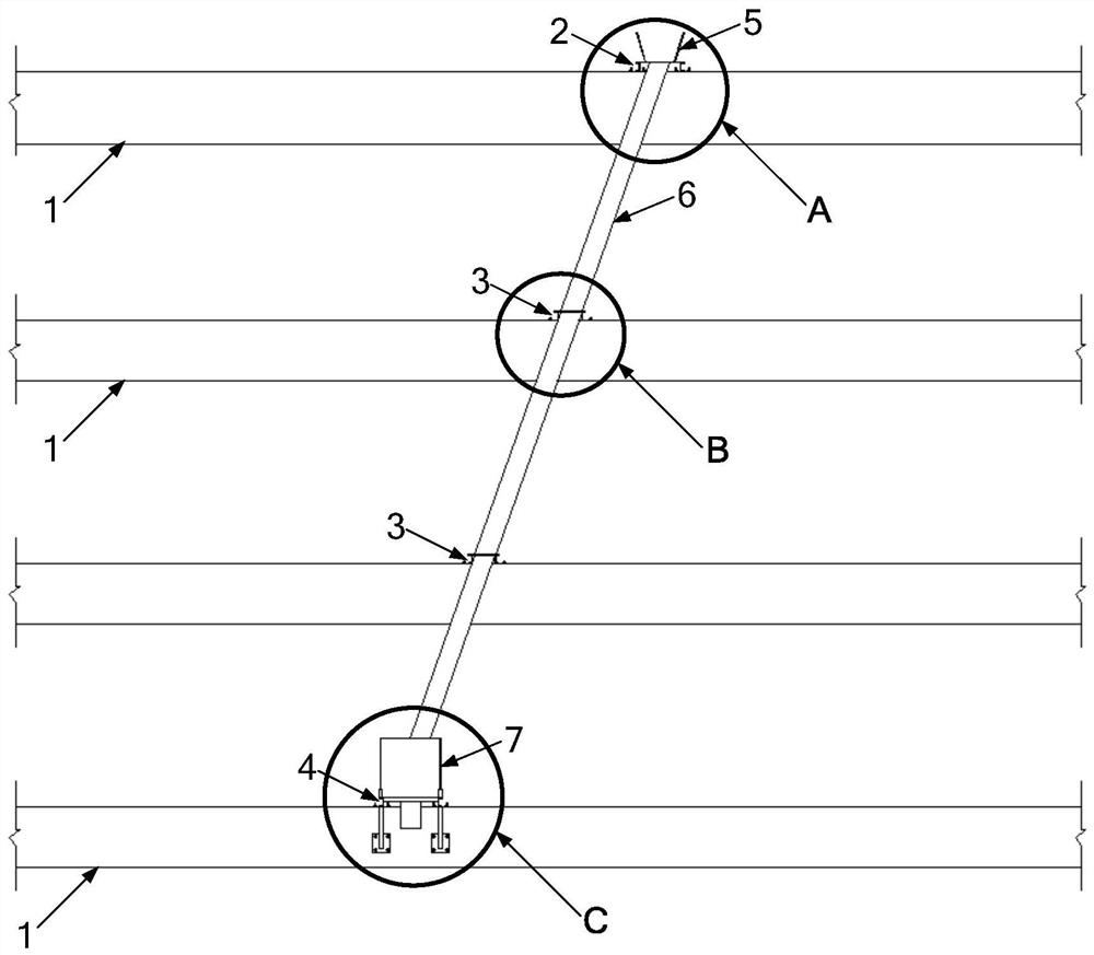
[0046] In order to solve the problems of unfavorable traffic, low pouring efficiency and unqualified pouring quality caused by the narrow construction site when pouring the existing foundation pit floor, the present invention provides a multi-support beam deep foundation pit floor concrete pouring system and its construction Methods: The concrete pouring system adopts cantilevered concrete conveying channel and multi-channel supporting beams as supporting points, which reduces the occupation of the construction site and overcomes various problems caused by the narrow construction site.

[0047] The concrete pouring system and construction method of the deep foundation pit floor with multiple support beams will be further described below with specific embodiments in conjunction with the accompanying drawings.

[0048] refer to Figure 11 Or as shown in 12, a deep foundation pit floor concrete pouring system with multiple support beams, including:

[0049] The first cantilever br...


PUM


Abstract

The invention relates to a deep foundation pit bottom plate concrete pouring system with multiple supporting beams and a construction method thereof. The concrete pouring system comprises a first cantilever bracket, at least one second cantilever bracket, a third cantilever bracket, an unloading hopper, a vertical concrete conveying pipe, a discharge hopper and a horizontal concrete conveying pipe, wherein the first cantilever bracket is fixed to an inner side of the upper supporting beam in an overhanging mode, the second cantilever brackets are fixed on the inner side of at least one supporting beam in the middle in a one-to-one overhanging mode, the third cantilever bracket is fixed on the inner side of the lower supporting beam in an overhanging manner, the unloading hopper is arranged at the overhanging end of the first cantilever bracket, the vertical concrete conveying pipe is fixed to overhanging ends of all the second cantilever brackets, an inlet of the vertical concrete conveying pipe communicates with an unloading opening of the unloading hopper, the discharge hopper is arranged at the overhanging end of the third cantilever bracket, a feeding port of the discharge hopper communicates with an outlet of the vertical concrete conveying pipe, and the horizontal concrete conveying pipe is supported at the bottom of a foundation pit through a plurality of adjusting supports with different heights, an inlet of the horizontal concrete conveying pipe communicates with a discharge port of the discharge hopper, and an outlet of the horizontal concrete conveying pipe points to a to-be-poured point. According to the concrete pouring system, the occupation of a construction site is reduced, and the problems caused by a small construction site are solved.

Description

technical field [0001] The invention relates to the field of construction engineering foundation pit construction, in particular to a multi-support beam deep foundation pit floor concrete pouring system and a construction method thereof. Background technique [0002] With the continuous development of the construction engineering industry, the depth of the foundation pit is getting deeper and deeper, and the geological conditions are more complex, which puts forward higher requirements for the support structure and internal support system. At present, ultra-deep foundation pits in riprap landfill areas generally adopt the support form of "ground connection wall + steel column + concrete support", and the number of support layers is usually more, and most of them are "ring support + straight support + diagonal support + Plane layout form of plank support. The complex support system brings great difficulties to the use of the sky pump for pouring. The arm of the sky pump is d...

Claims


Application Information

Patent Timeline
IPC IPC(8): E02D15/02
CPCE02D15/02E02D2250/0023
Inventor 彭申陈勇谢永光秦永晖姜文王旭毅邱威熊伟朱桂成卢建文梁思龙
Owner CHINA CONSTR EIGHT ENG DIV CORP LTD
Why Eureka
Try Eureka