
Dust removal equipment for cement manufacturing and processing

A technology of dust removal equipment and cement, which is applied to the separation of dispersed particles, chemical instruments and methods, combined devices, etc., can solve the problems of dust falling on the ground, difficulty in cleaning, and low efficiency, and achieve simple operation, convenient use, and fast cementing The effect of absorbing and filtering

Inactive Publication Date: 2021-11-19
金建华
View PDF0 Cites 0 Cited by
  • Summary
  • Abstract
  • Description
  • Claims
  • Application Information

AI Technical Summary

Problems solved by technology

[0004] The purpose of the present invention is to solve the existing shortcomings that most of the cement dust in the air is treated by spraying, the efficiency is not high, and the dust falls on the ground and it is difficult to clean up. Dust removal equipment for cement manufacturing and processing

Method used


Image

  • Dust removal equipment for cement manufacturing and processing
  • Dust removal equipment for cement manufacturing and processing
  • Dust removal equipment for cement manufacturing and processing

Examples


Embodiment 1

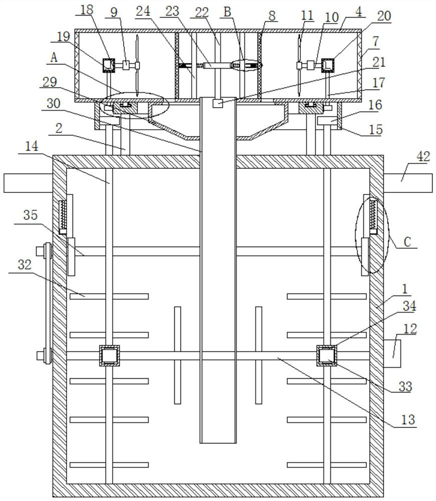
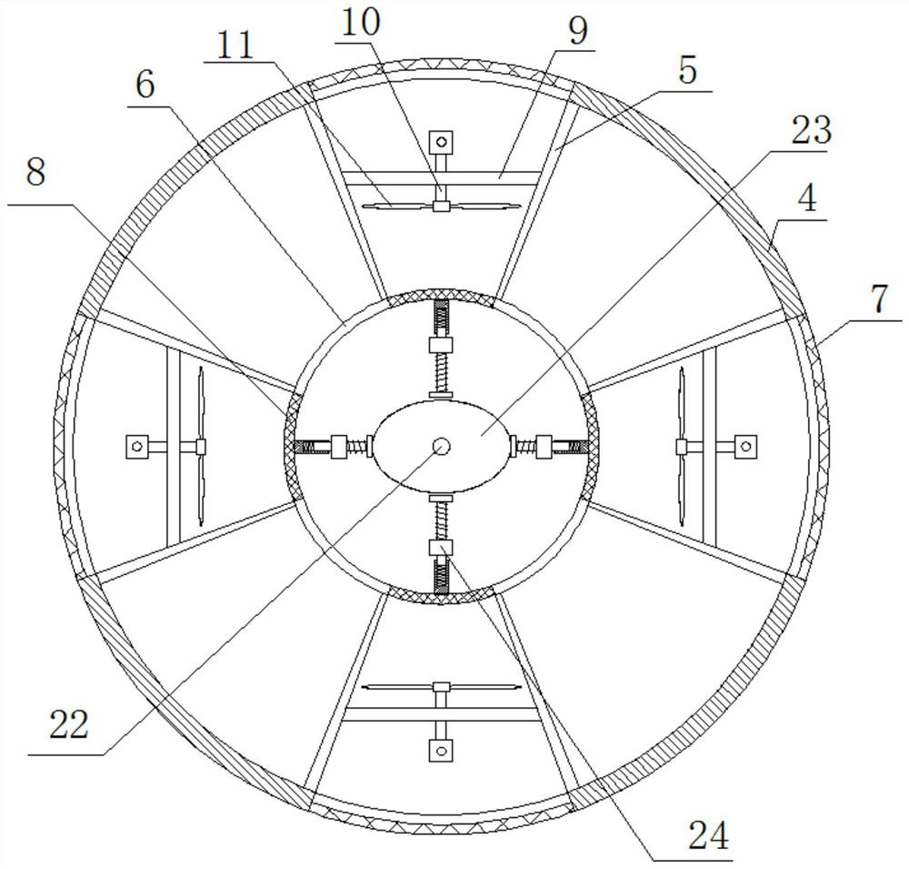
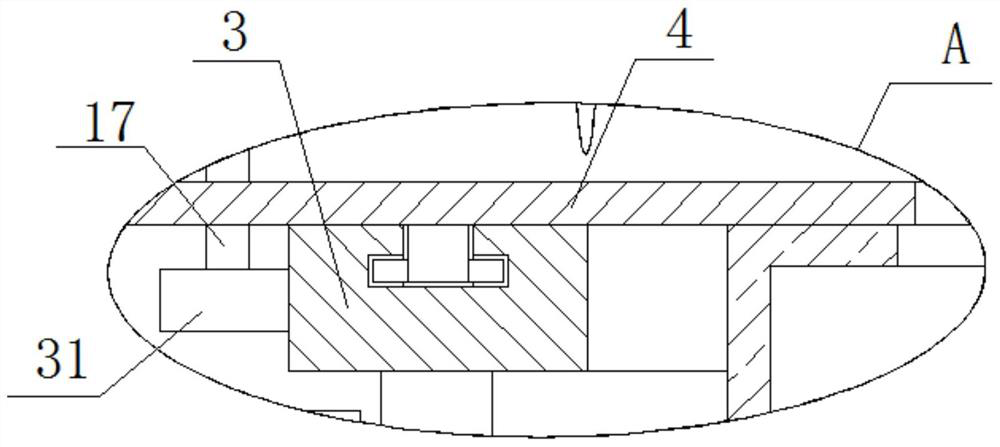
[0029] refer to Figure 1-5 , a dust removal device for cement manufacturing and processing, including a box body 1, four symmetrically arranged support rods 2 are fixedly installed on the top of the box body 1, and the same fixed ring 3 is fixedly installed on the top ends of the four support rods 2, The top of the fixed ring 3 is rotatably connected with the air intake box 4, and the inner wall of the air intake box 4 is fixedly equipped with an annular baffle plate 6, and a plurality of dividing plates 5 are fixedly installed between the annular baffle plate 6 and the air intake box 4, corresponding An isolation net 7 and a filter screen 8 are arranged between the two partitions 5, and the same fixed rod 9 is fixedly installed between the corresponding two partitions 5, and the fixed rod 9 is rotatably connected with a positioning shaft 10, and on the positioning shaft 10 The fan blade 11 is fixedly installed, and the top of the box body 1 is fixedly equipped with an air in...

Embodiment 2

[0040] refer to Figure 1-5 , a dust removal device for cement manufacturing and processing, including a box body 1, four symmetrically arranged support rods 2 are welded on the top of the box body 1, and the same fixed ring 3 is welded on the top ends of the four support rods 2, and the fixed ring The top of 3 is rotatably connected with an air intake box 4, and an annular baffle 6 is welded on the inner wall of the air intake box 4, and a plurality of baffles 5 are welded between the annular baffle 6 and the air intake box 4, and the corresponding two baffles 5 is provided with an isolation net 7 and a filter net 8, and the same fixed rod 9 is welded between the corresponding two partitions 5, and the fixed rod 9 is rotatably connected with a positioning shaft 10, and a fan blade 11 is welded on the positioning shaft 10. , the top of the box body 1 is welded with an air inlet pipe 30, the air inlet pipe 30 is rotationally connected with the air inlet box 4, and the air inlet...


PUM


Abstract

The invention belongs to the technical field of dust removal equipment, particularly relates to dust removal equipment for cement manufacturing and processing, and provides the following scheme aiming at the problems that when cement dust in air is treated in the prior art, most of the cement dust is treated through spraying, the efficiency is not high, and the dust falls on the ground and is difficult to clean. The equipment comprises a box body, four symmetrically-arranged supporting rods are fixedly installed at the top of the box body, the same fixing ring is fixedly installed at the top ends of the four supporting rods, an air inlet box is rotationally connected to the top of the fixing ring, an annular baffle is fixedly installed on the inner wall of the air inlet box, and a plurality of partition plates are fixedly installed between the annular baffle and the air inlet box. A separation net and a filter net are arranged between every two corresponding partition plates, and the same fixing rod is fixedly installed between every two corresponding partition plates. The equipment is easy to operate and convenient to use, air in a workshop can be rapidly subjected to cement absorption filtration and collection treatment, and people can use the equipment conveniently.

Description

technical field [0001] The invention relates to the technical field of dust removal equipment, in particular to a dust removal equipment used for cement manufacturing and processing. Background technique [0002] The dust produced in the cement production process, when the skin is covered with dust, can cause dermatitis, especially in summer, when the dust is used to block pores, it can cause rhinitis. Alkaline dust can cause skin dryness in winter, in order to reduce dust For the hazard of the split body, it is necessary to remove the dust. [0003] Most of the existing cement dust in the air is treated by spraying, which is not efficient, and it is difficult to clean the dust on the ground. Therefore, we propose a dust removal equipment for cement manufacturing and processing. Contents of the invention [0004] The purpose of the present invention is to solve the existing shortcomings that most of the cement dust in the air is treated by spraying, the efficiency is not ...

Claims


Application Information

Patent Timeline
IPC IPC(8): B01D50/00
Inventor 金建华
Owner 金建华
Learn More