Cutting machine for steel strands in anchor recesses of railway box girder

A steel strand and cutting machine technology, applied in the field of cutting devices, can solve the problems of high labor intensity, high safety risk, inability to cut steel strands accurately and efficiently, and achieve the effect of reducing labor intensity

Active Publication Date: 2021-11-19
THE SECOND CONSTR OF CTCE GROUP +2
View PDF7 Cites 0 Cited by
  • Summary
  • Abstract
  • Description
  • Claims
  • Application Information

AI Technical Summary

Problems solved by technology

In the current cutting process of anchor hole steel strands, most of them are cut by manual hand-held cutting machines, which have the disadvantages of low work efficiency, high labor intensity, and high safety risks.
It is difficult to adapt to the running displacement of the small space in the anchor hole by using a general mechanical cutting device, so the steel strands in the anchor hole cannot be cut accurately and efficiently

Method used


Image

  • Cutting machine for steel strands in anchor recesses of railway box girder
  • Cutting machine for steel strands in anchor recesses of railway box girder
  • Cutting machine for steel strands in anchor recesses of railway box girder

Examples


Embodiment

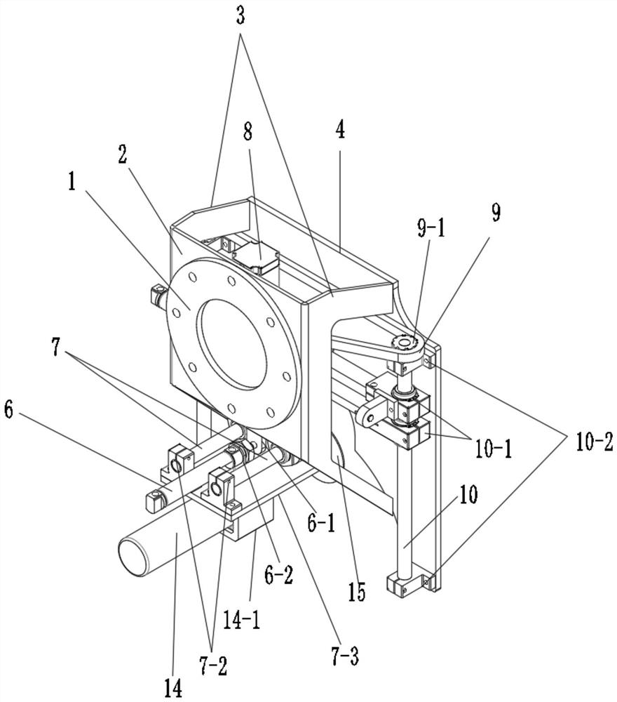
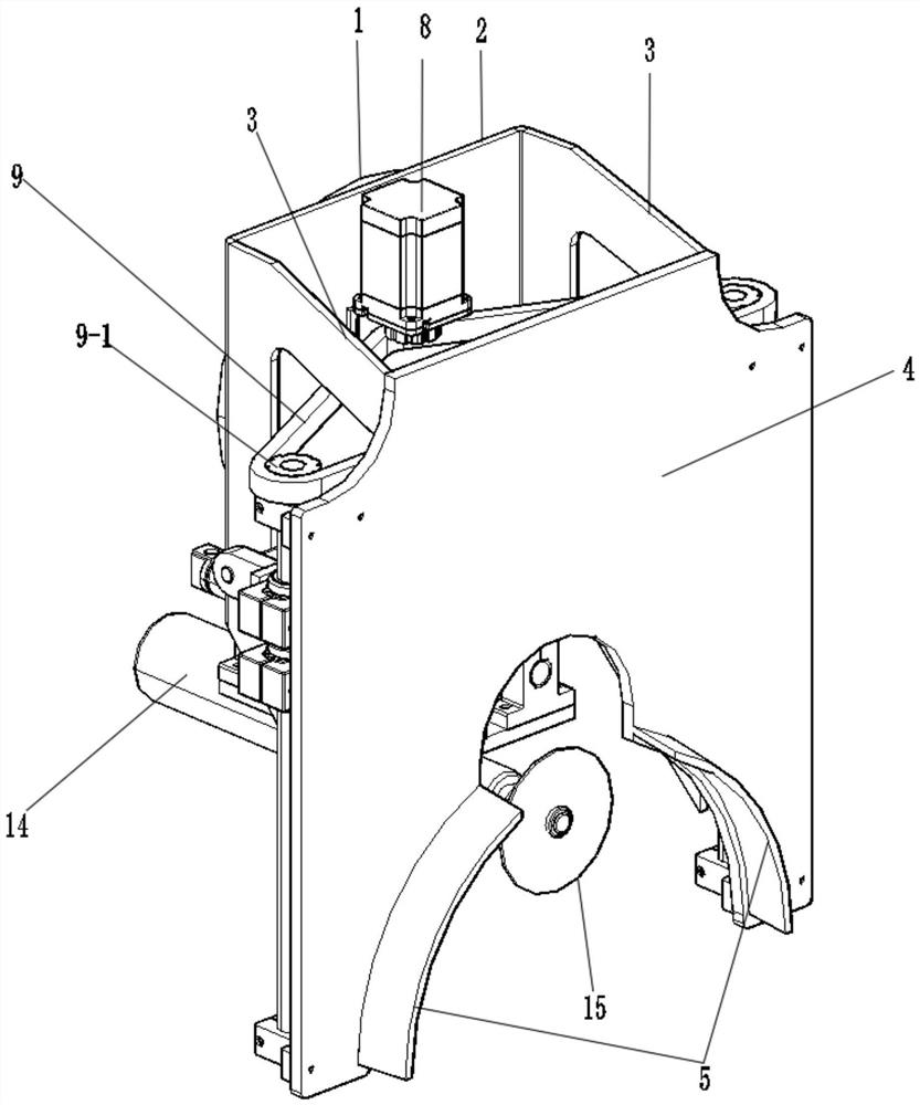
[0021] The cutting machine for the steel strand of the railway box girder anchor hole of the present embodiment, such as figure 1 and figure 2 As shown, it includes plate frame mechanism, up and down movement mechanism, left and right movement mechanism, front and rear movement mechanism and cutting mechanism. The plate and frame mechanism includes a flange plate 1, a back plate 2, a rib plate 3, a baffle plate 4, and a positioning clamp plate 5. The flange 1 and the back plate 2 are fixedly connected, the baffle 4 is parallel to the back plate 2, the ribs 3 are located between the baffle 4 and the back plate 2 and are connected vertically with the baffle 4 and the back plate 2 respectively, and the ribs The plates 3 are in the shape of two C-shaped plates facing each other in parallel. The back plate 2, the rib plate 3 and the baffle 4 form a frame cover structure, and the positioning clamp 5 is arranged on the outer surface of the baffle 4. arm.

[0022] Such as figure ...


PUM


Abstract

The invention relates to a cutting machine for steel strands in anchor recesses of a railway box girder, and belongs to the technical field of cutting devices. The cutting machine comprises a plate frame mechanism, an up-and-down moving mechanism, a left-and-right moving mechanism, a front-and-back moving mechanism and a cutting mechanism, wherein the cutting mechanism comprises a cutting motor and a cutting blade, and the cutting blade is installed at the output end of the cutting motor; the cutting mechanism is fixedly connected with the front-and-back moving mechanism, a front-and-back moving pair is formed between the front-and-back moving mechanism and the left-and-right moving mechanism, and a left-and-right moving pair and an up-and-down moving pair are formed between the left-and-right moving mechanism and the up-and-down moving mechanism respectively; and the plate frame mechanism can be connected with a mechanical arm. The cutting machine can accurately and effectively cut the steel strands in anchor recesses, and the labor intensity of cutting the steel strands in the anchor recesses is greatly reduced.

Description

technical field [0001] The invention relates to a machine for cutting steel strands in anchor holes on the end faces of railway prefabricated box girders, and belongs to the technical field of cutting devices. Background technique [0002] my country's railway construction accounts for a large proportion of bridges, most of which are simply supported beam bridges with standard spans. The construction of these bridges requires the manufacture of a large number of prefabricated box girders for railways. In the manufacture of railway prefabricated box girders, after demoulding, concrete pouring needs to go through processes such as tensioning, grouting, cutting of steel strands, chiseling and sealing of anchor hole holes, among which cutting of anchor steel strands requires mechanical cutting. In the current cutting process of anchor hole steel strands, most of them are cut by manual hand-held cutting machines, which have the disadvantages of low work efficiency, high labor in...

Claims


Application Information

Patent Timeline
Patent Type & Authority Applications(China)
IPC IPC(8): B21F11/00B23D19/00B23D33/02B23Q5/28
CPCB21F11/00B23D19/00B23D33/02B23Q5/28
Inventor 李勇海余秀平刘宁徐波吕瑞梁超陈平王杰刘其李宝蕴葛艳庆王和欢杨嘉毅江胜华林超李景杰刘少波万红斌杨刚施炎坤郑广涛
Owner THE SECOND CONSTR OF CTCE GROUP
Why Eureka
Try Eureka