Tool for cutting gear and method for cutting gear

a gear and gear cutting technology, applied in the direction of gear teeth, gear teeth, manufacturing tools, etc., can solve the problems of long machining time, difficult manufacturing and management of tools, and inconvenient mass production of machining cutting, etc., to achieve efficient cutting of skew gears

Active Publication Date: 2017-01-10
OGASAWARA PRECISION LABORATORY CO LTD
View PDF18 Cites 0 Cited by
  • Summary
  • Abstract
  • Description
  • Claims
  • Application Information

AI Technical Summary

Benefits of technology

[0008]The present invention has been made in view of the above circumstances. The object of the present invention is to provide a tool for precisely, efficiently cutting a skew gear, in particular, a face gear, to be meshed with a helical gear, and a method for cutting the face gear.

Problems solved by technology

The gear cutting by means of a shaper cutter of item (2) is not often utilized at present, because its machining efficiency is unsatisfactory, a tooth flank modification is difficult, only few suitable machines (shaper machines) are present, manufacture and management of a tool (helical pinion cutter) are difficult, and so on.
However, since it takes a long time for machining, the machining cutting is not suited for mass production.

Method used


Image

  • Tool for cutting gear and method for cutting gear
  • Tool for cutting gear and method for cutting gear
  • Tool for cutting gear and method for cutting gear

Examples


Embodiment Construction

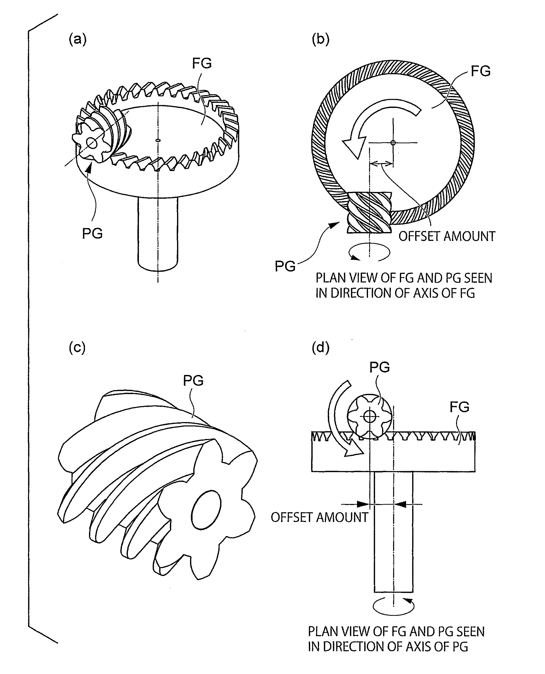
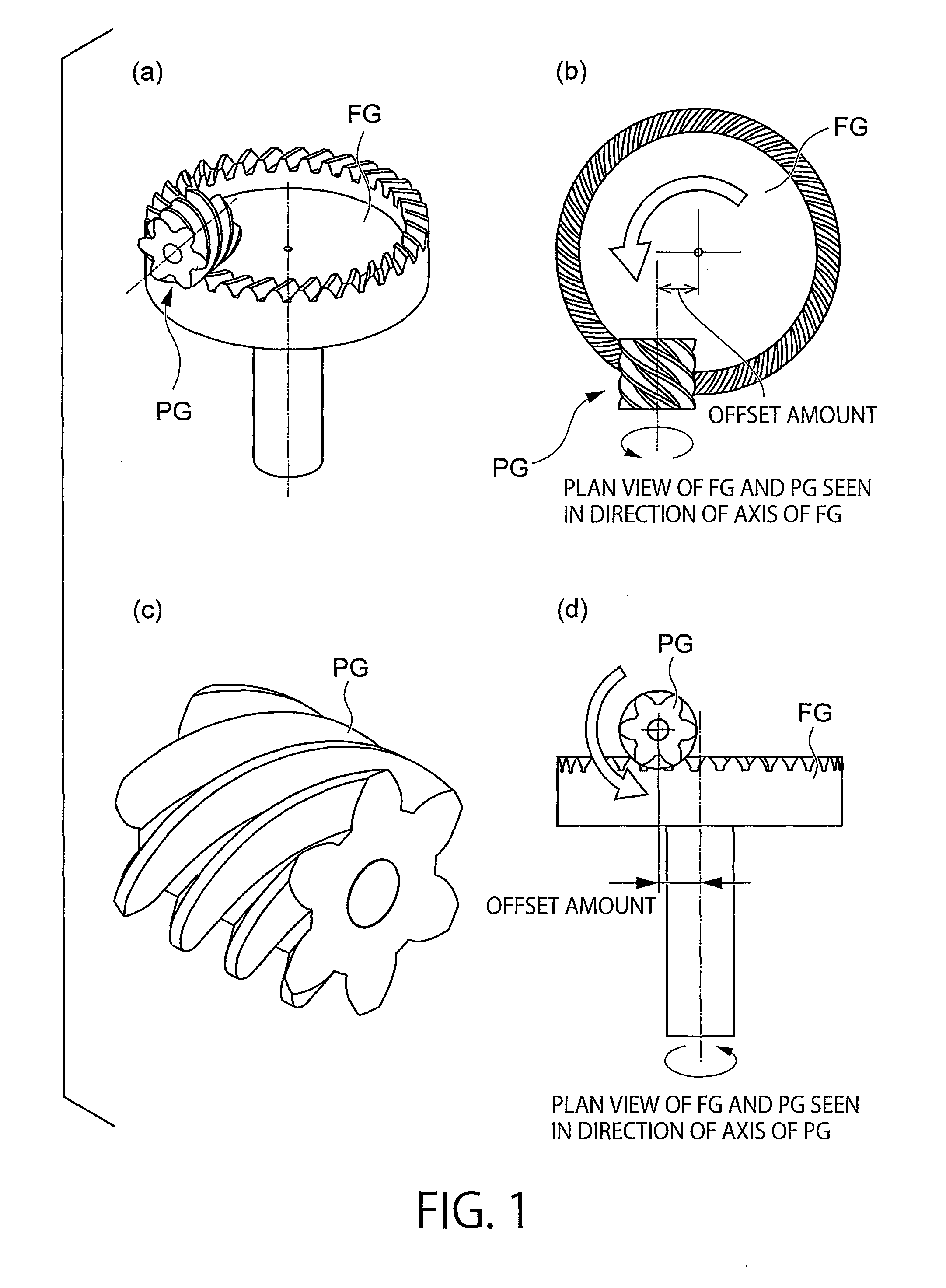
[0069]A tool according to one embodiment of the present invention is called “cutter having a spur gear shape SC”, which is a tool to be meshed with a gear to be cut so as to cut the same. Herein, the gear to be cut generally means a gear that can be accurately meshed with a helical gear. In the present invention, a face gear FG is employed as the gear to be cut.

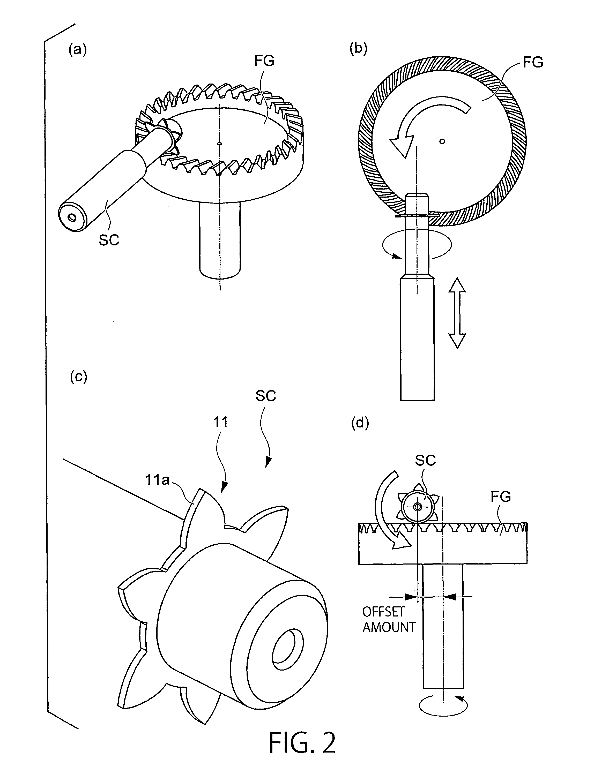
[0070]FIGS. 1(a) to 1(d) show a general face gear FG to be meshed with a helical pinion gear PG in an offset manner. FIGS. 2(a) to 2(d) show the cutter having a spur gear shape SC for cutting the face gear FG, which is located on a cutting position. As shown in FIGS. 2(a) to 2(d), the most standard function of the cutter having a spur gear shape SC in this embodiment is to cut the face gear FG to be meshed with the helical pinion gear PG, by means of cutting edges of a spur gear shape.

[0071]The cutter having a spur gear shape SC in this embodiment is a tool for cutting, as a gear to be cut, a gear to be meshed with the predet...


PUM

PropertyMeasurementUnit
thicknessaaaaaaaaaa
tooth depthaaaaaaaaaa
depthaaaaaaaaaa

Abstract

There is provided a tool for efficiently cutting a face gear to be meshed with a helical gear. When a circular tooth thickness of a tooth tip of a cutting edge portion is represented as SatSC, a circular tooth thickness on a virtual outside diameter of a tooth profile of the helical gear in a cross-sectional view perpendicular to an axis is represented as Sat, a helix angle on the virtual outside diameter of the tooth profile of the helical gear in a cross-sectional view by a plane perpendicular to the axis is represented as βa, and a face width of the cutting edge portion is represented as bsc,bSC≦sat-satSCtan⁢⁢βais satisfied.

Description

CROSS-REFERENCE TO RELATED APPLICATIONS[0001]This application claims priority to Japanese Patent Application No. 2012-112867 filed on May 16, 2012, the disclosure of which is hereby incorporated by reference in its entirety.FIELD OF THE INVENTION[0002]The present invention relates to a tool for cutting a gear and a method for cutting a gear. In particular, the present invention relates to a tool for cutting a face gear to be meshed with a helical gear whose axis is not parallel to that of the face gear, and a method for cutting the face gear.BACKGROUND ART[0003]Face gears (Crown gears), which are one kind of gears, are widely used in the field of driving wheels mainly used in spinning reels for fishing in Japan. However, in recent years, usefulness of the face gears has been widely regarded, and the face gears have been developed or used also in the field of gearboxes with orthogonal axes and the field relating to aircrafts.[0004]As methods for machining a face gear, the following t...

Claims


Application Information

Patent Timeline
Patent Type & Authority Patents(United States)
IPC IPC(8): B23F21/00B23F21/16B23F21/12B23F15/06B23F9/08B23F21/10
CPCB23F21/166B23F9/082B23F15/06B23F21/122B23F21/16Y10T407/173Y10T409/101749B23F5/20B23F21/04B23F21/06
Inventor OGASAWARA, HIROOMI
Owner OGASAWARA PRECISION LABORATORY CO LTD
Why Eureka
Try Eureka