Actuator

A technology of actuators and sliding parts, which can be used in transmission devices, bearings for linear motion, rotating parts that resist centrifugal force, etc., and can solve problems such as increased working resistance of balls

Pending Publication Date: 2021-11-19
SMC CORP
View PDF2 Cites 0 Cited by
  • Summary
  • Abstract
  • Description
  • Claims
  • Application Information

AI Technical Summary

Problems solved by technology

In this case, when the guide rail is bent or warped, there is a problem that the working resistance of the balls increases

Method used


Image

  • Actuator
  • Actuator
  • Actuator

Examples


Embodiment Construction

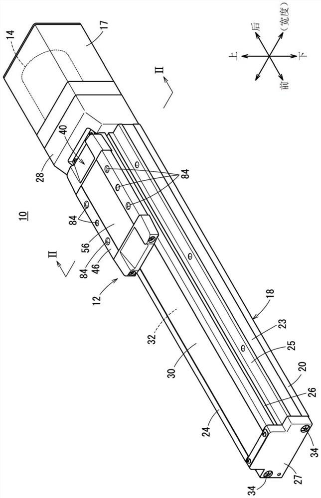
[0034] Hereinafter, preferred embodiments will be cited, and the actuator according to the present invention will be described in detail with reference to the drawings. Also, the following "front" is from figure 1 The direction away from the motor 14 is shown, and "rear" indicates the direction approaching the motor 14 . In addition, "down" and "up" are vertical directions perpendicular to the front-rear direction. Also, the "width direction" is a horizontal direction perpendicular to the front-back direction. Although the above directions are shown in each drawing, these directions are for the convenience of simplifying the description and facilitating understanding, and do not particularly designate the directions when the actuator is actually used.

[0035] figure 1 It is a schematic overall perspective view of the actuator 10 according to the first embodiment. The actuator 10 is configured as a linear actuator including a linear guide 12 extending in the front-rear dir...


PUM


Abstract

The present invention provides an actuator capable of avoiding an increase in the operating resistance of a ball even when a guide rail is bent or warped, and capable of achieving miniaturization and weight reduction. The actuator (10) is provided with a main body (18) and a slider (40). A main body-side rail groove (90) is formed in side wall sections (22, 23) constituting the main body (18). A slider-side rail groove (128) is formed in the slider (40). A main body-side guide rail (100) and a slider-side guide rail (140) are provided in the main body-side rail groove (90) and the slider-side rail groove (128). Arc grooves (152, 154), which are ball grooves, are formed by main body-side ball support parts (114, 116) of the main body-side guide rail (100) and slider-side ball support parts (146, 148) of the slider-side guide rail (140).

Description

technical field [0001] The invention relates to an actuator having a body and a slider moving in an interior space within the body. Background technique [0002] An actuator having a main body and a slider moving in an internal space within the main body is being widely used as, for example, a conveying mechanism for conveying workpieces. In this type of actuator, a table is provided on the slider, and a workpiece is held on the table. As the slider moves integrally with the table, the workpiece is conveyed. [0003] Ball grooves having a substantially semicircular cross-section perpendicular to the moving direction of the slider are respectively formed in the main body and the slider, and balls made of bearing steel or the like are inserted into the ball grooves. The slider moves smoothly by rolling the balls in the ball grooves. In addition, a circulation passage for circulating the balls is formed on the slider. After rolling in the ball groove, the ball returns to th...

Claims


Application Information

Patent Timeline
Patent Type & Authority Applications(China)
IPC IPC(8): B65G35/00B65G47/74
CPCB65G35/00B65G47/74F16C29/063F16C33/585F16C33/586F16C33/62F16C2204/20F16C2204/70F16C2240/40F16C2322/39F16C29/08F16H2025/204F16H2025/2075F16C29/082F16C29/005
Inventor 佐藤俊夫古宇田直树宫原正树今村正树三田刚
Owner SMC CORP
Why Eureka
Try Eureka