Crane counterweight structure and stabilizing method

A crane and counterweight technology, used in cranes, load hanging elements, transportation and packaging, etc., can solve the problems of falling off surrounding people and buildings, crane counterweights, fixed cranes, etc., to reduce weight and reduce oil. Loss and shedding prevention effect

Pending Publication Date: 2021-11-19
安徽江河智能装备集团有限公司
View PDF0 Cites 0 Cited by
  • Summary
  • Abstract
  • Description
  • Claims
  • Application Information

AI Technical Summary

Problems solved by technology

[0004] This solution solves the problem that the traditional crane counterweight is inconvenient to be fixed on the bottom of the crane during the installation process due to the heavy weight of the crane. At the same time, when the crane starts to work and lift, the crane counterweight is affected by gravity and centrifugal force It is easy to fall off and cause damage to surrounding people and buildings

Method used


Image

  • Crane counterweight structure and stabilizing method
  • Crane counterweight structure and stabilizing method
  • Crane counterweight structure and stabilizing method

Examples


Embodiment 1

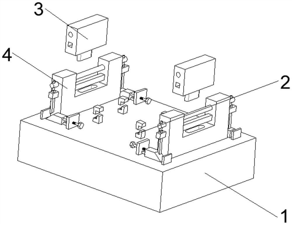
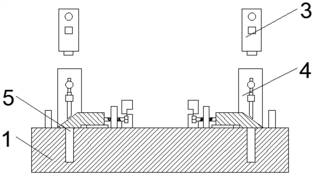
[0033] The above-mentioned fixing mechanism 4 includes a mounting plate 402 fixedly connected with the counterweight 1, the top surface of the mounting plate 402 is provided with a mounting groove 401, the bottom of the groove wall of the mounting groove 401 is provided with a limiting groove 405, and the inside of the mounting groove 401 is provided with The first connecting rod 403 with a circular longitudinal section and the second connecting rod 404 with a rectangular longitudinal section, both ends of the first connecting rod 403 and the second connecting rod 404 move through the mounting plate 402, and the Limiting mechanisms 406 are provided on both sides.

[0034] The above-mentioned clamping block 3 includes a block body 301 located above the mounting plate 402, the top of the block body 301 is fixedly connected with the external crane, the bottom of the block body 301 is fixedly installed with a limit block 302, and the position of the limit block 302 and the limit gr...

Embodiment 2

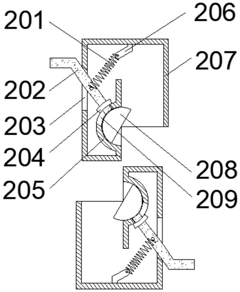
[0038] The above-mentioned connecting mechanism 2 includes a shell 207 fixedly connected to the counterweight 1 or one of the external cranes. One side of the shell 207 is provided with an opening, and a connecting plate 205 is fixedly installed at the opening. Circular rotating slot, the inside of the rotating slot is movably connected with a rotating block 208 with a semicircular section, the groove wall of the rotating slot is provided with a first limiting hole 209, and the inside of the first limiting hole 209 is provided with a rotating rod 202, the other side of the shell 207 is provided with a second limit hole 203, the inside of the shell 207 is provided with a moving cavity, the cavity wall of the moving cavity is fixedly installed with a connecting seat 206, and one end of the rotating rod 202 is fixedly connected with the rotating block 208, The other end of the rotating rod 202 moves through the second limiting hole 203, and the middle part of the rotating rod 202 ...


PUM


Abstract

The invention relates to a crane counterweight structure and a stabilizing method. The crane counterweight structure comprises a counterweight block, fixing mechanisms are arranged at the two ends of the top face of the counterweight block, clamping blocks are arranged between the two fixing mechanisms and an external crane, and four connecting mechanisms corresponding to one another in position are arranged in the middle of the top face of the counterweight block and at the bottom of an external crane. Through mutual clamping of openings of two corresponding shells and cooperation with contraction of a tension spring, two rotating blocks are connected with corresponding rotating grooves in a clamped mode, the two connecting mechanisms corresponding in position are relatively fixed, the follow-up positioning effect needed by an installation plate and a block body is facilitated, the time needed by clamping of the installation plate and the block body is shortened; and a first limiting rod and a second limiting rod movably penetrate through the ends of a first connecting rod and a second connecting rod, an inclined block is pushed to a first baffle, the first limiting rod is supported by the inclined block, the first limiting rod and the second limiting rod are prevented from falling off, and therefore the stability of the counterweight block is improved.

Description

technical field [0001] The invention relates to the field of crane counterweights, in particular to a crane counterweight structure, and more specifically to a crane counterweight structure and a stabilizing method. Background technique [0002] The stability of the whole crane is one of the key indicators affecting the hoisting performance of the crane. Therefore, when designing the crane, the weight of the counterweight is often increased to the limit that the axle can carry to maximize the stability of the whole machine. . [0003] Due to the heavy crane counterweight, it is inconvenient to fix the traditional crane counterweight on the bottom of the crane during installation. At the same time, when the crane starts to work and lift, the crane counterweight is affected by gravity and centrifugal force, which is prone to Falling off causes damage to surrounding people and buildings. Contents of the invention [0004] This solution solves the problem that the traditiona...

Claims


Application Information

Patent Timeline
IPC IPC(8): B66C23/72B66C13/00
CPCB66C23/72B66C13/00
Inventor 梁大伟
Owner 安徽江河智能装备集团有限公司
Why Eureka
Try Eureka