
Electroslag remelting device and method for preventing segregation of remelted alloy

An electroslag remelting and remelting technology, applied in the field of electroslag remelting, can solve the problems of poor solidification quality of electroslag ingots and low electroslag remelting efficiency.

Active Publication Date: 2021-11-19
ANHUI FUKAI STAINLESS STEEL
View PDF13 Cites 0 Cited by
  • Summary
  • Abstract
  • Description
  • Claims
  • Application Information

AI Technical Summary

Problems solved by technology

[0008] Aiming at the problems of low remelting efficiency and poor solidification quality of electroslag ingots in the electroslag remelting device or method in the prior art, the present invention provides an electroslag remelting device and method for preventing segregation of remelted alloys; The magnetic field is set in the slag pool of the melting part and the metal molten pool forming the electroslag ingot, and the power supply for heating the slag and melting the electrode and the power supply for refining the solidified structure are set independently of each other, thus effectively solving the problem of the existing technology. The problems of low electroslag remelting efficiency and poor solidification quality of electroslag ingots

Method used


Image

  • Electroslag remelting device and method for preventing segregation of remelted alloy
  • Electroslag remelting device and method for preventing segregation of remelted alloy
  • Electroslag remelting device and method for preventing segregation of remelted alloy

Examples


Embodiment 1

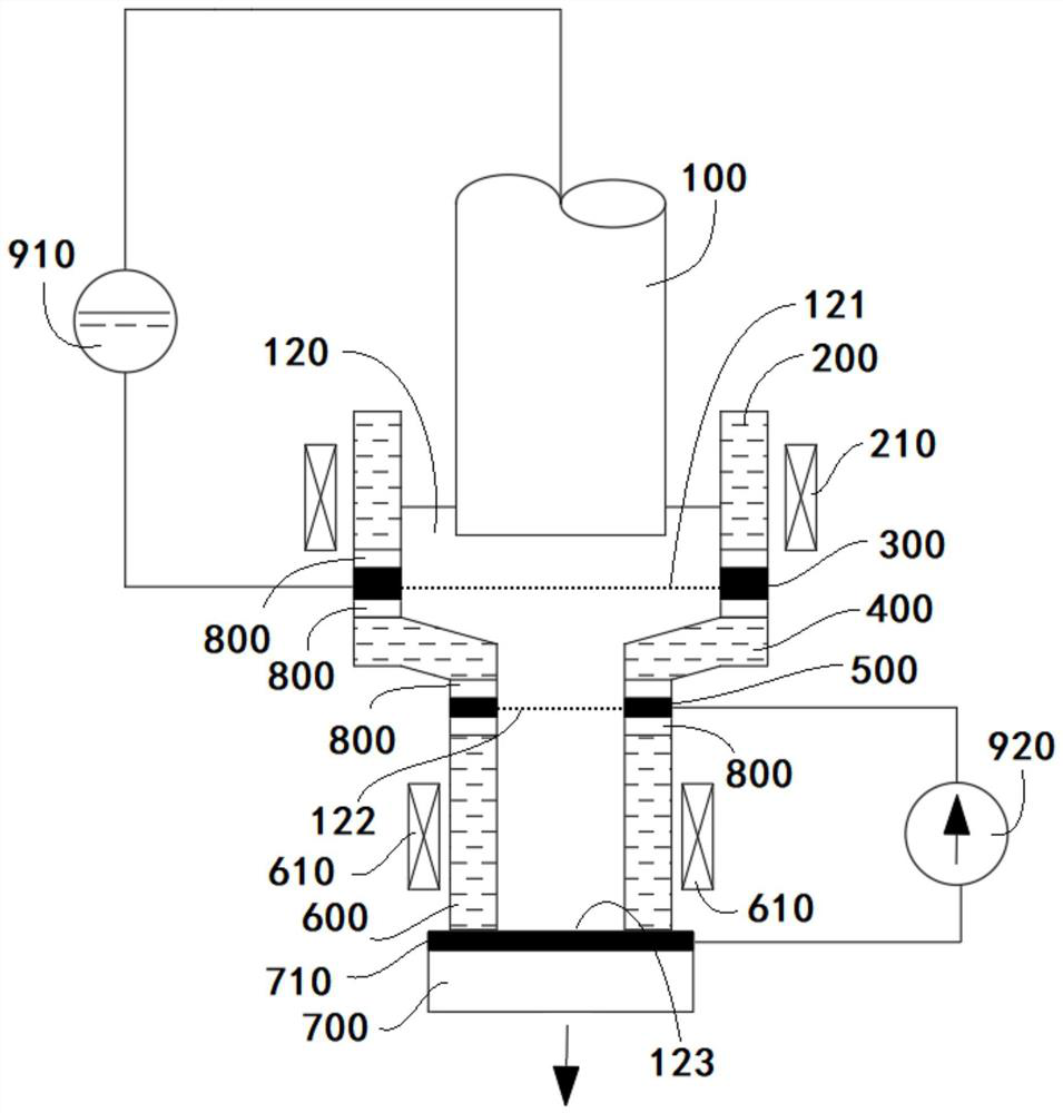
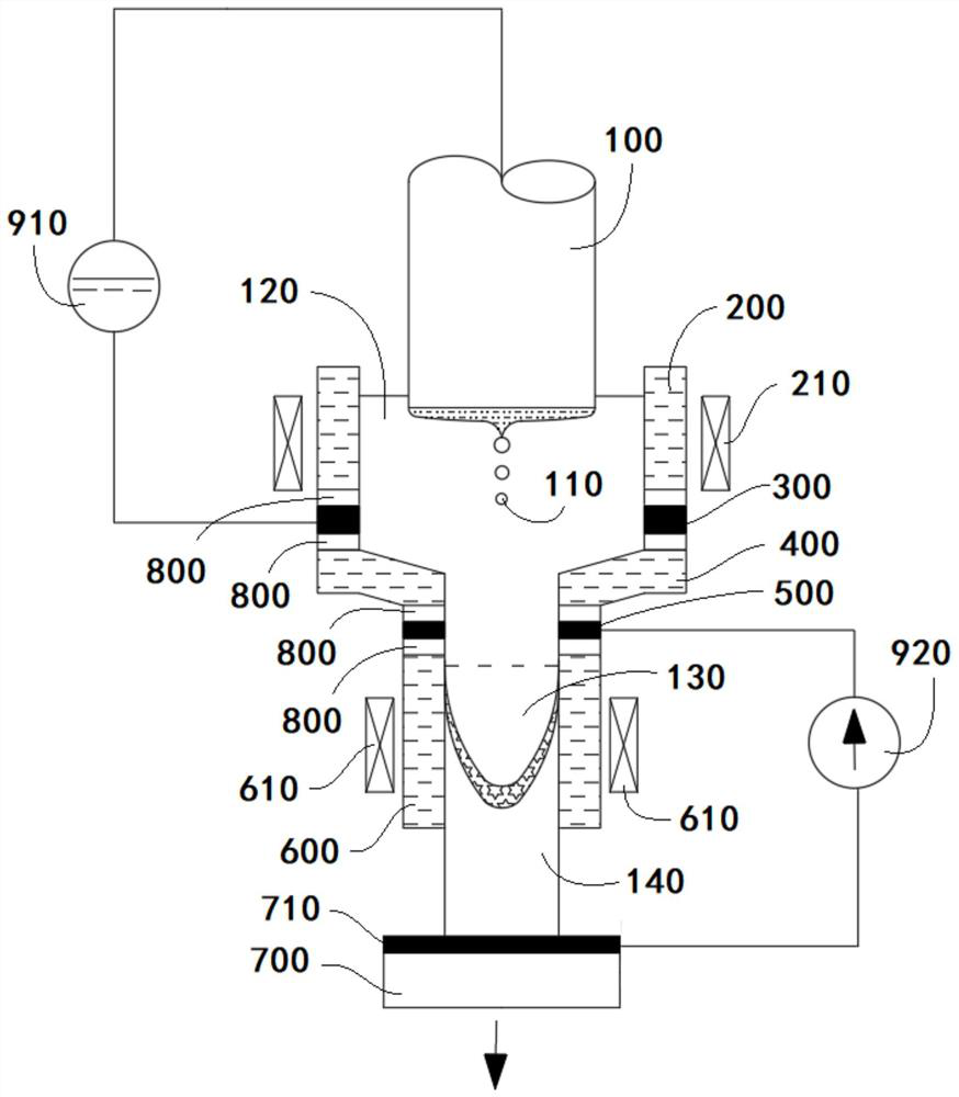
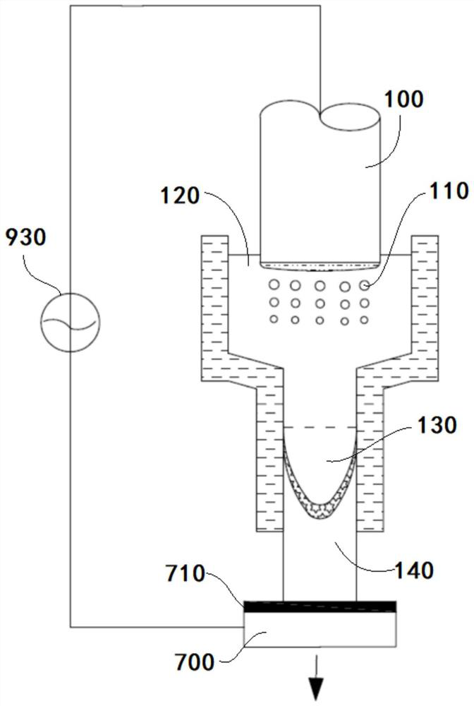
[0054] This embodiment provides an electroslag remelting device for preventing segregation of remelted alloys, such as figure 1 and figure 2 As shown, it includes a crystallizer, a power supply, a magnetic field unit and a sump tank 700 . The crystallizer is arranged on the bottom water tank 700, which is used to provide cold energy to the crystallizer to solidify the metal to form an electroslag ingot; the top of the bottom water tank 700 is provided with a conductive layer 710.

[0055] The crystallizer comprises a first crystallizer 200, a transition crystallizer 400 and a second crystallizer 600 from top to bottom. The first crystallizer 200 in this embodiment is cylindrical, and its diameter is D1=600mm. The second crystallizer 200 is cylindrical, its diameter is D2=200mm, and the D1 / D2=3.5:1; as other embodiments of the present invention, the D1 / D2 can be 3:1 or 4:1; because The diameter of the first crystallizer 200 is larger, so the diameter of the consumable electr...


PUM

PropertyMeasurementUnit
diameteraaaaaaaaaa

Abstract

The invention discloses an electroslag remelting device and method for preventing segregation of a remelted alloy, and belongs to the technical field of electroslag remelting. The electroslag remelting device comprises a crystallizer, a power supply and a magnetic field unit; the crystallizer sequentially comprises a first crystallizer, a transition crystallizer and a second crystallizer from top to bottom; the first crystallizer is connected with the transition crystallizer in an insulating manner, and the transition crystallizer is connected with the second crystallizer in an insulating manner; in a slag bath, a first slag bath layer is arranged at the position corresponding to the bottom of the first crystallizer, a second slag bath layer is arranged at the position corresponding to the top of the second crystallizer, and a third slag bath layer is arranged at the bottom layer; the power supply comprises a first power supply and a second power supply; a consumable electrode is connected with the first slag bath layer through the first power supply; and the second slag bath layer is connected with the third slag bath layer through the second power supply. According to the electroslag remelting device and method for preventing the segregation of the remelted alloy, the problem that molten metal is bonded with the crystallizer can be effectively avoided, meanwhile, the remelting efficiency is improved, and the solidification quality of an electroslag ingot is improved.

Description

technical field [0001] The invention belongs to the technical field of electroslag remelting, and more specifically relates to an electroslag remelting device and a method thereof for preventing segregation of remelted alloys. Background technique [0002] Many high-quality materials such as high-temperature alloys, high-speed steel, and stainless steel are produced by electroslag remelting technology. However, electroslag remelting technology also has many advantages, such as low remelting efficiency and high production costs, which reduce the competitiveness of products to a certain extent. For this reason, the rapid electroslag remelting technology was developed, which broke through the rule that the ratio of the melting speed to the diameter of the electroslag ingot does not exceed 1, and the remelting speed was greatly increased. The core of rapid remelting is that the diameter of the slag pool is larger than that of the electroslag ingot. However, this technology has...

Claims


Application Information

Patent Timeline
Patent Type & Authority Applications(China)
IPC IPC(8): C22B9/18C22B9/187
CPCC22B9/18
Inventor 施晓芳常立忠
Owner ANHUI FUKAI STAINLESS STEEL
Learn More