Supercharge Your Innovation With Domain-Expert AI Agents!

Improved self-control heat dissipation brake drum

A brake drum, an improved technology, applied in the direction of brake type, brake parts, brake drum, etc., to avoid poor braking effect, improve heat dissipation effect, and improve heat dissipation effect

Pending Publication Date: 2021-11-19
河北百龙汽车配件股份有限公司
View PDF7 Cites 0 Cited by
  • Summary
  • Abstract
  • Description
  • Claims
  • Application Information

AI Technical Summary

Problems solved by technology

[0004] The technical problem to be solved by the present invention is to provide an improved self-control heat dissipation brake drum in view of the above-mentioned technical deficiencies. By arranging at least one heat dissipation shell on the outer circumference of the brake drum, the heat dissipation shell can be used to gather the airflow. And make it take away the heat generated by the brake, avoid the problem of the friction coefficient of the brake drum due to the high temperature, and effectively ensure the braking effect of the brake drum; The design is streamlined, and the rib at the air inlet is equipped with a windward part to reduce friction with the air. The opening direction of the air outlet is staggered from the air inlet, which can prevent hot air from entering from the previous air outlet to the next air inlet. The purpose of cooling the brake drum in time

Method used


Image

  • Improved self-control heat dissipation brake drum
  • Improved self-control heat dissipation brake drum
  • Improved self-control heat dissipation brake drum

Examples


Embodiment Construction

[0016] In order to make the technical solutions and advantages of the present invention clearer, the present invention will be further described in detail below in conjunction with specific embodiments and accompanying drawings. It should be understood that these descriptions are exemplary only, and are not intended to limit the scope of the present invention. Also, in the following description, descriptions of well-known structures and techniques are omitted to avoid unnecessarily obscuring the concept of the present invention.

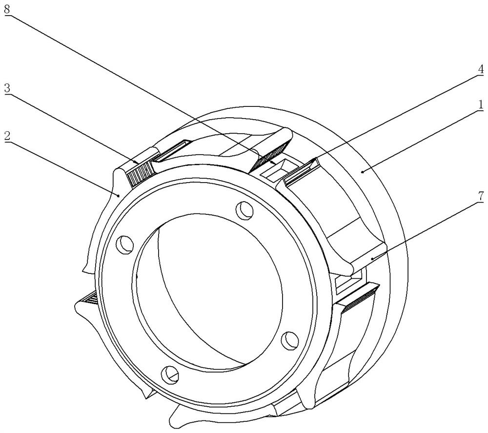
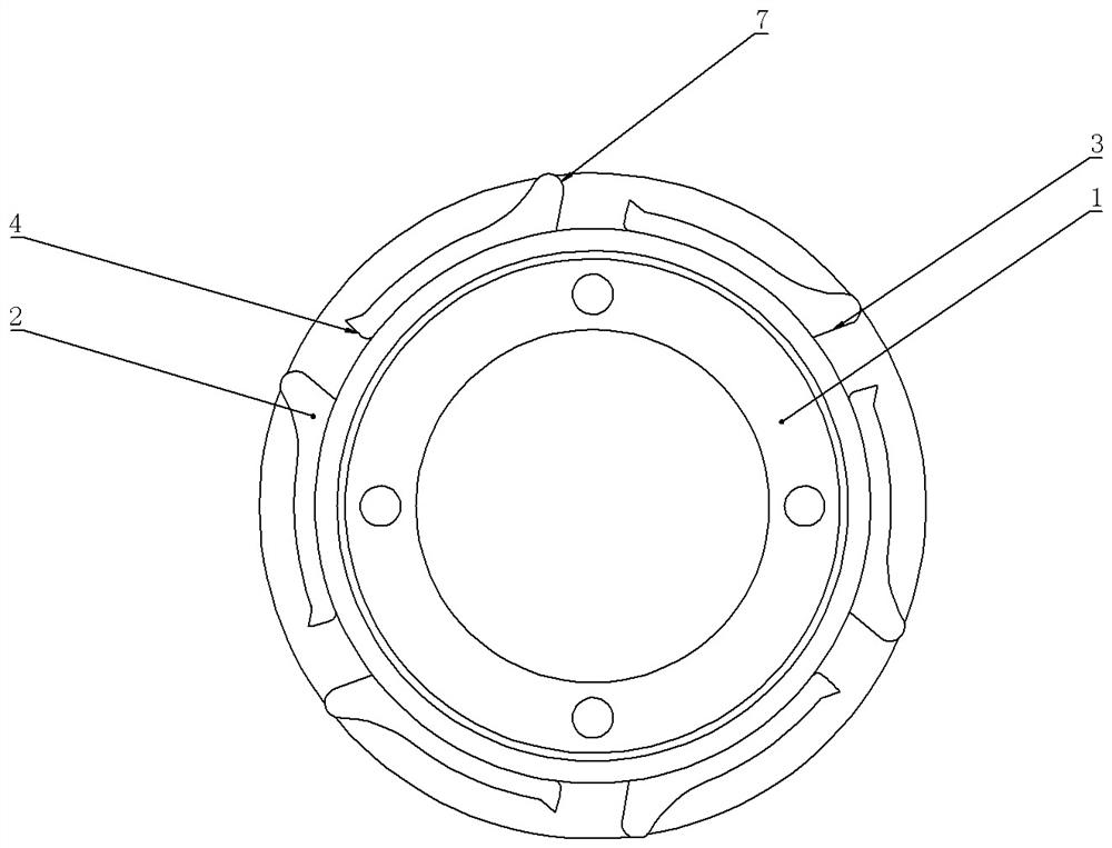
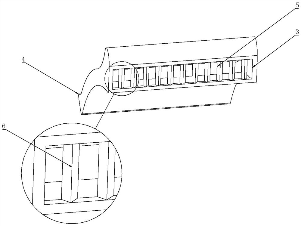
[0017] An improved self-control cooling brake drum, such as Figure 1 to Figure 3 as shown, figure 1 It is a schematic diagram of the overall structure of the improved self-control heat dissipation brake drum in the embodiment, which includes a brake drum body 1, and a heat dissipation shell 2 is arranged outside the brake drum body 1. The overall design of the heat dissipation shell 2 is streamlined, including two There are two ports of air inlet ...


PUM


Abstract

The invention relates to the technical field of brake drums, in particular to an improved self-control heat dissipation brake drum. At least one heat dissipation shell is arranged on the side face of a brake drum body in the circumferential direction, each heat dissipation shell is overall of a streamline design and is used for reducing heat generated by friction with air, an air inlet and an air outlet are formed in the two ends of each heat dissipation shell correspondingly, ribs are arranged at the air inlets, the side faces, close to the outside, of the ribs are provided with windward faces used for reducing air friction, and the opening directions of the air outlets are in the right-angle range of the sides close to the air inlets. The heat dissipation effect of the brake drum is greatly improved through the structural design, and the problem that the braking effect is poor due to the fact that the temperature is too high is solved.

Description

technical field [0001] The invention relates to the technical field of brake drums, in particular to an improved self-control heat dissipation brake drum. Background technique [0002] The brake drum is the friction couple of the drum brake. In addition to the strength and rigidity required as a component, it should also have as high and stable a friction coefficient as possible, as well as appropriate wear resistance, heat resistance, and heat dissipation. and heat capacity etc. The brake drum is also a component in the braking system to generate braking force that hinders the movement or movement tendency of the vehicle. Except for various slowing devices, the automobile brakes almost always use the friction between the fixed element and the working surface of the rotating element to generate braking torque. Friction brakes. [0003] If the brake drum is improperly designed, it is easy to deform when heated. When the temperature of the brake drum is too high, it will mak...

Claims


Application Information

Patent Timeline
Patent Type & Authority Applications(China)
IPC IPC(8): F16D65/10F16D65/827
CPCF16D65/10F16D65/827F16D2065/788F16D65/0031
Inventor 张彦彬
Owner 河北百龙汽车配件股份有限公司
Features
  • R&D
  • Intellectual Property
  • Life Sciences
  • Materials
  • Tech Scout
  • Unparalleled Data Quality
  • Higher Quality Content
  • 60% Fewer Hallucinations
Learn More