Blasting method for shallow-buried goaf of strip mine

A goaf and open-pit mine technology, applied in blasting, mining equipment, earthwork drilling, etc., can solve the problems of irregular mining of underground goafs, deep subsidence pits, mining equipment and personnel safety threats, etc., to reduce The amount of manual filling and leveling works, the construction safety environment is good, and the effect of reducing engineering costs

Active Publication Date: 2021-11-19
鞍钢矿业爆破有限公司
View PDF6 Cites 1 Cited by
  • Summary
  • Abstract
  • Description
  • Claims
  • Application Information

AI Technical Summary

Problems solved by technology

[0002] At present, there are many underground goafs in many mines. In recent years, due to the lack of centralized integration of mineral resources around the mines, irregular mining has further expanded the number of underground goafs. Instability is an extremely serious geological disaster in mines. Therefore, the existence of these goafs poses a serious threat to the safety of mine equipment and personnel, and also brings great difficulties to the organization and implementation of mining plans.
However, the current domestic mine engineering does not consider the filling efficiency when blasting and caving the goaf. For the shallow buried goaf after the roof blasting, the single goaf roof collapse technology is often used because the volume of the bulk is not enough to completely fill the goaf. As a result, deep subsidence pits are formed after the explosion, resulting in an increase in the amount of secondary manual filling, which not only fails to completely eliminate hidden dangers in production safety, but also increases the investment and construction period for goaf management

Method used


Image

  • Blasting method for shallow-buried goaf of strip mine
  • Blasting method for shallow-buried goaf of strip mine
  • Blasting method for shallow-buried goaf of strip mine

Examples


Embodiment 1

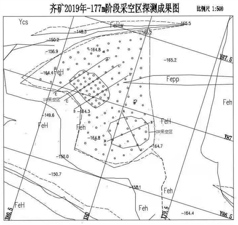
[0119] Qidashan Iron Mine -177m stage mined-out area blasting collapse design scheme:

[0120] The goaf processing blasting task goaf is located at the northern end of the -177m stage of Qi Mine, coordinates: y-8650~y-8750; x-7950~x-8050 area, according to the obtained detection data, at this stage the ore Two goafs were detected in the production site, namely Ⅰ# and Ⅱ# goafs. With the advancement of the stope working face, according to the mine production organization arrangement and the reality that the existing stope space is limited, the main transport road of the stope after the relocation will cross the upper part of the goaf. Effective governance will have brought a major threat to mine safety production.

[0121] Step 1. The ore body in this area is a large-scale thick-bedded ore body with a stable occurrence, a strike of 310°-340°, a strike extension of 4.6 kilometers, a dip angle of 70°-85°, a dip of 70° to 85°, a dip in the south-west or northeast, and a dip in dep...


PUM


Abstract

The invention provides a blasting method for a shallow-buried goaf of a strip mine and belongs to the technical field of engineering blasting. The blasting method comprises the following steps that step1, properties, occurrence conditions and geometric spatial characteristics of ores around the goaf are confirmed; step2, the safety thickness of a top plate above the goaf is confirmed, perforating equipment is selected, and a perforating scheme is designed; step3, hole net parameters of goaf top plate loose blasting and lateral throwing blasting are confirmed, and a charging structure and a detonating network are designed; step4, the muck pile size is estimated; step5, goaf volume balance calculation is performed, and the blasting collapse volume is confirmed; step6, blast hole arranging, charging and filling are performed; and step7, the detonating network is connected, detonating is performed, and the caving filling effect is observed and recorded. According to the blasting method for the shallow-buried goaf of the strip mine, the lateral free surface condition created by the underground goaf is fully utilized, lateral throwing filling is assisted while top plate caving filling is implemented, single-side, double-side or multi-side lateral blasting throwing filling can be implemented, the filling rate of the underground goaf is increased, and secondary manual filling is reduced or avoided.

Description

technical field [0001] The invention belongs to the technical field of engineering blasting, and in particular relates to a blasting method for a shallow-buried goaf in an open-pit mine. Background technique [0002] At present, there are many underground goafs in many mines. In recent years, due to the lack of centralized integration of mineral resources around the mines, irregular mining has further expanded the number of underground goafs. Instability is an extremely serious geological disaster in mines. Therefore, the existence of these goafs poses a serious threat to the safety of mine equipment and personnel, and also brings great difficulties to the organization and implementation of mining plans. However, the current domestic mine engineering does not consider the filling efficiency when blasting and caving the goaf. For the shallow buried goaf after the roof blasting, the single goaf roof collapse technology is often used because the volume of the bulk is not enough...

Claims


Application Information

Patent Timeline
Patent Type & Authority Applications(China)
IPC IPC(8): F42D1/00F42D1/08F42D3/04F42D3/00E21F17/00
CPCF42D1/00F42D1/08F42D3/04F42D3/00E21F17/00
Inventor 梁尔祝徐淼耿威王锐谷传宝曹洋
Owner 鞍钢矿业爆破有限公司
Why Eureka
Try Eureka