Alignment method of liquid crystal panel, liquid crystal panel and display device

A liquid crystal panel and liquid crystal technology, applied in nonlinear optics, instruments, optics, etc., can solve the problems of reducing transmittance, etc., and achieve the effect of increasing transmittance, reducing exposure dark lines, and strengthening alignment force

Pending Publication Date: 2021-11-19
CHENGDU ZHONGDIAN PANDA DISPLAY TECH CO LTD
View PDF0 Cites 0 Cited by
  • Summary
  • Abstract
  • Description
  • Claims
  • Application Information

AI Technical Summary

Problems solved by technology

[0004] However, in the UV2A exposure method of the above-mentioned "目" shape, dark lines of exposure are formed at the division of pixels, thereby reducing the transmittance

Method used


Image

  • Alignment method of liquid crystal panel, liquid crystal panel and display device
  • Alignment method of liquid crystal panel, liquid crystal panel and display device
  • Alignment method of liquid crystal panel, liquid crystal panel and display device

Examples


no. 1 example

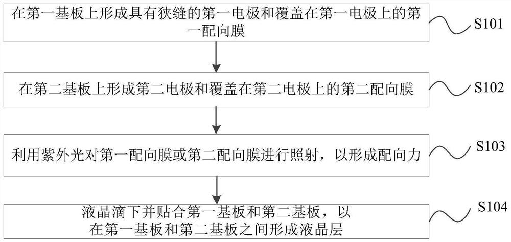
[0056] figure 2 A flowchart of an alignment method for a liquid crystal panel provided by an embodiment of the present invention; image 3 It is a schematic structural diagram of a liquid crystal panel aligned by an alignment method of a liquid crystal panel provided by an embodiment of the present invention. see figure 2 and image 3 As shown, the embodiment of the present invention provides a liquid crystal panel alignment method, including the following steps:

[0057] S101 , forming a first electrode having a slit and a first alignment film covering the first electrode on a first substrate.

[0058] Specifically, the first substrate 20 may be an array substrate (also called a TFT substrate). The first substrate 20 is covered with a first electrode 202 , and the first electrode 202 is covered with a first alignment film 201 . In a specific implementation, the first electrode 202 is a transparent electrode, and the transparent electrode may use an ITO thin film. ITO ...

no. 2 example

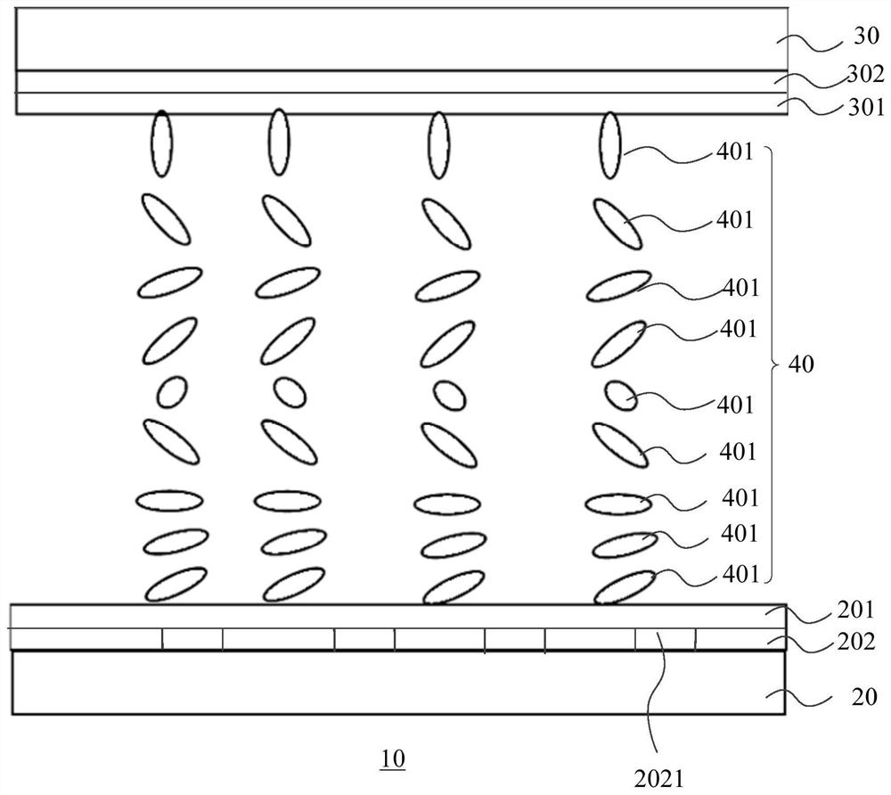
[0080] Figure 8 A position diagram of the first ultraviolet light irradiation in an alignment method of a liquid crystal panel provided by an embodiment of the present invention; Figure 9 for Figure 8 Schematic diagram of the rotation of chiral liquid crystal molecules in Figure 12 for Figure 8 Schematic diagram of the rotation of nematic liquid crystal molecules. see Figure 8 As shown, the steps of the first alignment method can be,

[0081] S201 , forming a first electrode 202 having a slit 2021 and a first alignment film 201 covering the first electrode 202 on the first substrate 20 . Wherein, the width of the slit 2021 is 3.0 μm, and the distance between two adjacent slits 2021 is 6.5 μm.

[0082] S202 , forming a second electrode 302 and a second alignment film 301 covering the second electrode 302 on the second substrate 30 .

[0083] S303, irradiating the first substrate 20 with ultraviolet light.

[0084] S304 , the liquid crystal is dropped and attached ...

no. 3 example

[0091] Figure 13 A position map of the second ultraviolet light irradiation in an alignment method of a liquid crystal panel provided by an embodiment of the present invention; Figure 14 for Figure 13 Schematic diagram of the rotation of chiral liquid crystal molecules in ; Figure 16 for adoption Figure 13 The rendering of a pixel in the alignment method. see Figure 13 and Figure 16 As shown, the steps in the second alignment method can be,

[0092] S301 , forming a first electrode 202 having a slit 2021 and a first alignment film 201 covering the first electrode 202 on the first substrate 20 . Wherein, the width of the slit 2021 is 3.0 μm, and the distance between two adjacent slits 2021 is 6.5 μm.

[0093] S302 , forming a second electrode 302 and a second alignment film 301 covering the second electrode 302 on the second substrate 30 .

[0094] S303, irradiating the second substrate 30 with ultraviolet light.

[0095] S304 , the liquid crystal is dropped and...


PUM

PropertyMeasurementUnit
thicknessaaaaaaaaaa
thicknessaaaaaaaaaa

Abstract

The invention provides an alignment method of a liquid crystal panel, the liquid crystal panel and a display device. The alignment method of the liquid crystal panel comprises the following steps of forming a first electrode with a slit and a first alignment film covering the first electrode on a first substrate, forming a second electrode on the second substrate and a second alignment film covering the second electrode, irradiating the first alignment film or the second alignment film by using ultraviolet light to form alignment force, and enabling the liquid crystal to drop and be attached to the first substrate and the second substrate, so that a liquid crystal layer is formed between the first substrate and the second substrate. According to the alignment method of the liquid crystal panel provided by the invention, the exposure dark lines at the segmentation positions of the pixels can be reduced, so that the transmittance is improved.

Description

technical field [0001] The invention relates to the technical field of display equipment manufacturing, in particular to an alignment method of a liquid crystal panel, a liquid crystal panel and a display device. Background technique [0002] Liquid Crystal Display (LCD) has many advantages such as thin body, power saving, and no radiation, and has been widely used, such as LCD TV, mobile phone, personal digital assistant, digital camera, computer screen or notebook computer screen, etc. . At present, TFT-LCD liquid crystal panels can be divided into three categories, namely twisted nematic / super twisted nematic (TN / STN) type, in-plane switching (IPS) type and vertical alignment (VA) type. While ultraviolet induced multi-domain vertical alignment (ultraviolet induced multi-domain vertical alignment, UV 2 A) is a photo-alignment technology for VA-type liquid crystal panels. Its name comes from the multiplication of ultraviolet UV and VA mode of liquid crystal panels. Its pr...

Claims


Application Information

Patent Timeline
Patent Type & Authority Applications(China)
IPC IPC(8): G02F1/1337G02F1/1341
CPCG02F1/133788G02F1/1341G02F1/133707
Inventor 李凡李广圣戴明鑫神户诚叶宁李向峰张勇彭林张世强王志刚薛彦鹏南明智
Owner CHENGDU ZHONGDIAN PANDA DISPLAY TECH CO LTD
Why Eureka
Try Eureka