Thread binding method and device and electronic equipment

A thread and binding technology, applied in the direction of multi-program device, program control design, program startup/switching, etc., can solve problems affecting CPU efficiency, dynamic binding, CPU waste, etc., and achieve the goal of improving execution efficiency and efficient execution Effect

Pending Publication Date: 2021-11-19
ZHEJIANG DAHUA TECH CO LTD
View PDF0 Cites 1 Cited by
  • Summary
  • Abstract
  • Description
  • Claims
  • Application Information

AI Technical Summary

Problems solved by technology

[0002] In the Linux operating system, each CPU has its own run queue, and threads in the ready state share a certain CPU. These threads are scheduled in turn within one CPU cycle, and the CPU is allocated to each thread according to the priority of the thread. The higher the thread priority, the more CPU time it can occupy in a scheduling cycle. When the CPU is scheduled from one thread to the next thread, it needs to perform thread context switching. Excessive thread switching will lead to Frequent context switching causes CPU to be wasted in the context switching process irrelevant to business, affecting CPU efficiency;
[0003] At present, a method of binding CPUs with multi-queue network cards is adopted. One CPU can run multiple threads, and multiple threads in the CPU run queue can still run in turn. The network card receiving thread is frequently interrupted by other threads, resulting in The processing efficiency of the CPU on the packet receiving thread of the network card is low
[0004] In addition, a data compression method is adopted, which binds the CPU core and the compression transaction thread in advance, and does not dynamically bind other business threads with high CPU usage according to the actual business situation of the system. , the current CPU is still bound, so the current CPU will be idle. At this time, threads with high CPU usage cannot be bound to the current CPU, resulting in low CPU processing efficiency for threads.

Method used


Image

  • Thread binding method and device and electronic equipment
  • Thread binding method and device and electronic equipment
  • Thread binding method and device and electronic equipment

Examples


Embodiment Construction

[0039] In order to make the purpose, technical solution and advantages of the application clearer, the application will be further described in detail below in conjunction with the accompanying drawings. The specific operation methods in the method embodiments can also be applied to the device embodiments or system embodiments. It should be noted that in the description of the present application, "plurality" is understood as "at least two". "And / or" describes the association relationship of associated objects, indicating that there may be three types of relationships, for example, A and / or B may indicate: A exists alone, A and B exist simultaneously, and B exists independently. The connection between A and B can mean: A and B are directly connected and A and B are connected through C. In addition, in the description of the present application, words such as "first" and "second" are only used for the purpose of distinguishing descriptions, and cannot be understood as indicati...


PUM


Abstract

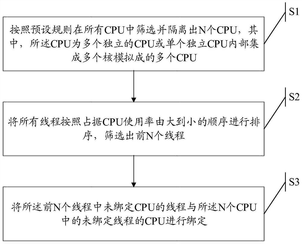
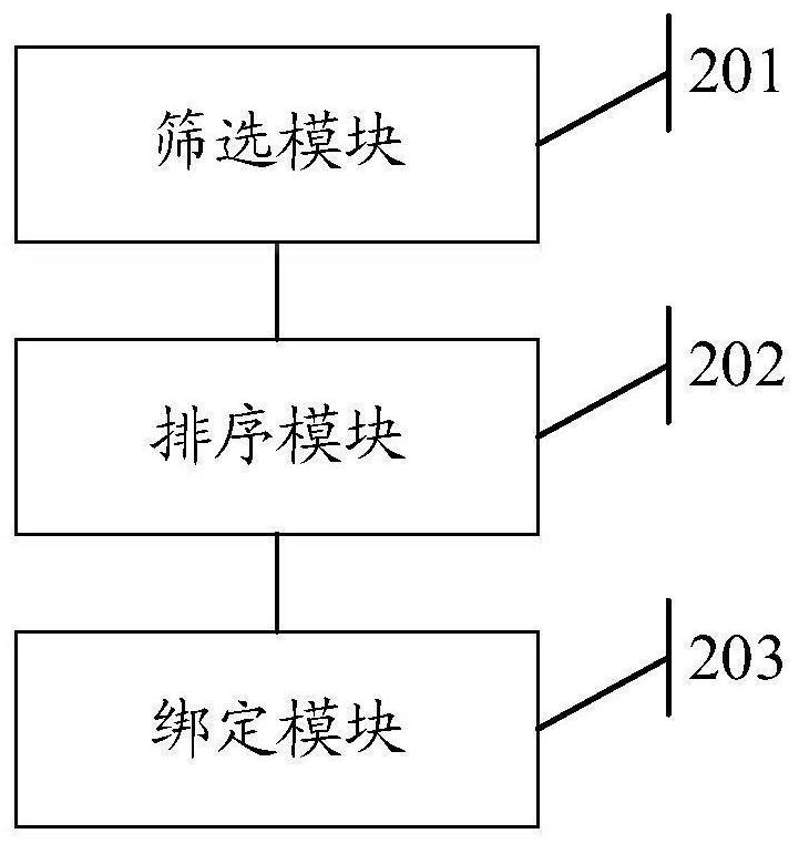
The invention discloses a thread binding method and device and electronic equipment. The method comprises the steps that N CPUs are screened and isolated from all the CPUs according to preset rules, all the threads are sorted according to the sequence of occupying the utilization rates of the CPUs from large to small, the first N threads are screened out, and the threads, not bound with the CPUs, in the first N threads are bound with the CPUs, not bound with the threads, in the N CPUs. By means of the method, the CPUs and the threads with the same number are screened out, the first N threads with the highest CPU occupancy rate in the system are circularly obtained according to the preset period, the binding states of the N CPUs and the N threads are checked, it is ensured that the N CPUs and the N threads with the high CPU occupancy rate can be bound in a one-to-one mode, and therefore bidirectional binding of the CPUs and the threads is achieved, the threads can be efficiently executed on the CPUs, and the execution efficiency of the threads and the thread processing efficiency of the CPUs are improved.

Description

technical field [0001] The present application relates to the technical field of data storage, and in particular to a thread binding method, device and electronic equipment. Background technique [0002] In the Linux operating system, each CPU has its own run queue, and threads in the ready state share a certain CPU. These threads are scheduled in turn within one CPU cycle, and the CPU is allocated to each thread according to the priority of the thread. The higher the thread priority, the more CPU time it can occupy in a scheduling cycle. When the CPU is scheduled from one thread to the next thread, it needs to perform thread context switching. Excessive thread switching will lead to Frequent context switching causes CPU to be wasted in the context switching process irrelevant to business, affecting CPU efficiency; [0003] At present, a method of binding CPUs with multi-queue network cards is adopted. One CPU can run multiple threads, and multiple threads in the CPU run qu...

Claims


Application Information

Patent Timeline
Patent Type & Authority Applications(China)
IPC IPC(8): G06F9/48G06F9/50
CPCG06F9/4881G06F9/5038G06F2209/5021
Inventor 滕开恩马东星魏齐良
Owner ZHEJIANG DAHUA TECH CO LTD
Why Eureka
Try Eureka