
Contact terminal automatic welding machine

An automatic welding machine and contact terminal technology, which is applied in the connection, electrical components, circuits, etc., can solve the problems of low work efficiency, high work intensity of workers, and difficult handling by tweezers, etc., to facilitate centralized collection and improve production and processing efficiency.

Pending Publication Date: 2021-11-19
ZHEJIANG JIAXING JINRONG AUTO PARTS CO LTD
View PDF6 Cites 0 Cited by
  • Summary
  • Abstract
  • Description
  • Claims
  • Application Information

AI Technical Summary

Problems solved by technology

[0003] The purpose of the present invention is to provide an automatic welding machine for contact terminals, which is used to solve the problem that the current parts welding device lacks an automatic feeding component, and the parts need to be manually carried by the staff. Small tweezers are not easy to carry, which affects the quality of the processed products. At the same time, the work intensity of the workers is high and the work efficiency is low.

Method used


Image

  • Contact terminal automatic welding machine
  • Contact terminal automatic welding machine
  • Contact terminal automatic welding machine

Examples


Embodiment Construction

[0024] In order to make the technical means, creative features, goals and effects achieved by the present invention easy to understand, the present invention will be further elaborated below in conjunction with illustrations and specific embodiments.

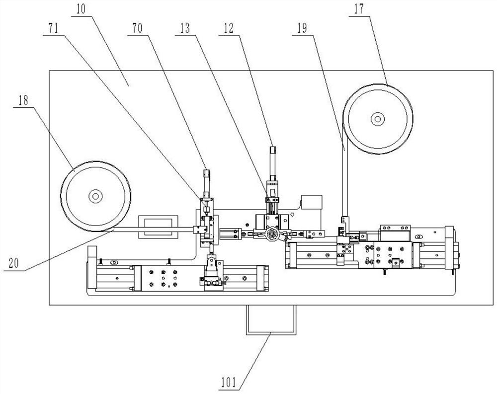
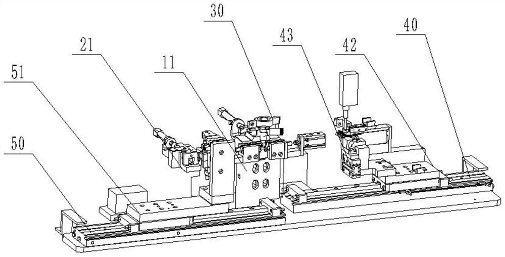
[0025] Such as Figure 1 to Figure 7 As shown, a contact terminal automatic welding machine of the present invention includes a workbench 10, a fixed block 11 is arranged on the workbench 10, and a pushing cylinder 12 is arranged on one side of the fixing block 11, and the pushing cylinder The output end of 12 is connected with one end of the pusher rod 13, and the other end of the pusher rod 13 extends to the outside through the fixed block 11. In this embodiment, the pusher cylinder 12 is a CDJ2B10-10 cylinder. A welding assembly is arranged above the pushing rod 13, and the input end of the welding assembly is connected with an external power source for welding the parts on the pushing rod 13. The end of the pushing rod 13 aw...


PUM


Abstract

The invention discloses a contact terminal automatic welding machine which comprises a workbench, wherein a fixing block is arranged on the workbench, a material pushing air cylinder is arranged on one side of the fixing block, a material pushing rod is arranged at the output end of the material pushing air cylinder, a welding assembly is arranged above the material pushing rod, a feeding assembly is arranged at the end, away from the material pushing air cylinder, of the material pushing rod, a first clamping air cylinder and a second clamping air cylinder are arranged on the two sides of the material pushing rod correspondingly, and fixing rods are arranged at the output end of the first clamping air cylinder and the output end of the second clamping air cylinder correspondingly; and the feeding assembly comprises a first vibration feeding disc and a second vibration feeding disc, a first feeding groove is formed in the output end of the first vibration feeding disc, a first feeding mechanism is arranged at the output end of the first feeding groove, a second feeding groove is formed in the output end of the second vibration feeding disc, and a storage table, a second feeding mechanism and a feeding mechanism are arranged at the output end of the second feeding groove. According to the contact terminal automatic welding machine, small parts needing to be welded can be precisely carried to the designated positions, the carrying speed is high, the welding precision is high, and the stability is high.

Description

technical field [0001] The invention relates to the field of welding technology, in particular to an automatic welding machine for contact terminals. Background technique [0002] Contact terminal welding is to connect and fuse two or more different mechanical parts by welding to form a workflow of a whole part. Large workpieces and welding are welded by staff with welding tools, while small parts are welded Work is usually performed on a welding bench. The current parts welding device lacks automatic feeding components, and the parts need to be manually carried by the staff. The touch of the workers will easily cause the parts to oxidize. The work intensity is high and the work efficiency is low. Therefore, it is necessary for us to improve such a structure to overcome the above-mentioned defects. Contents of the invention [0003] The purpose of the present invention is to provide an automatic welding machine for contact terminals, which is used to solve the problem t...

Claims


Application Information

Patent Timeline
Patent Type & Authority Applications(China)
IPC IPC(8): H01R43/02
CPCH01R43/02
Inventor 张振军
Owner ZHEJIANG JIAXING JINRONG AUTO PARTS CO LTD
Learn More