
Metal elastic sheet stamping die

A technology of stamping dies and metal shrapnel, which is applied in the field of stamping dies, can solve problems affecting the production efficiency of the production line, unfavorable continuous production of molds, and affecting the life of moving components, etc., so as to reduce the stoppage time of the assembly line, reduce the lubrication time of the stoppage, and reduce the maintenance cost effect

Active Publication Date: 2021-11-23
ANHUI UNIV OF SCI & TECH
View PDF10 Cites 0 Cited by
  • Summary
  • Abstract
  • Description
  • Claims
  • Application Information

AI Technical Summary

Problems solved by technology

[0003] During the shaping process of the shaping die, due to the stress of the upper stamping die, the stamped part is tightly attached to the surface of the lower die, resulting in the phenomenon that the mold cannot be demoulded, and the manipulator cannot grab the shaping part, that is, the next step cannot be carried out, resulting in The stoppage of the assembly line seriously affects the stamping efficiency. At the same time, during the stamping process, due to the multiple reciprocating movements of each component, it is necessary to manually lubricate the moving components through an oil gun. Failure to lubricate in time will easily lead to accelerated wear of the moving components and affect the life of the moving components. , and the equipment needs to be turned off when injecting oil through the oil gun, which is not conducive to the continuous production of the mold and affects the production efficiency of the production line

Method used


Image

  • Metal elastic sheet stamping die
  • Metal elastic sheet stamping die
  • Metal elastic sheet stamping die

Examples


Embodiment Construction

[0025] In order to make the technical means, creative features, goals and effects achieved by the present invention easy to understand, the present invention will be further described below in conjunction with specific embodiments.

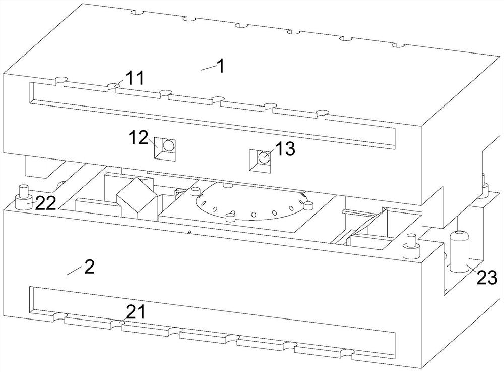
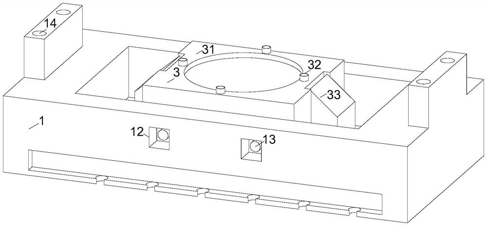
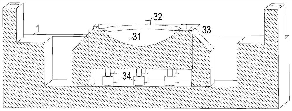
[0026] Such as Figure 1-Figure 8 As shown, a metal elastic stamping die according to the present invention includes an upper die 1 and a lower die 2, and the stamping die also includes a pressing mechanism 3 and a driven mechanism 5, and the upper die 1 and the lower die 2 are arranged in cooperation , the pressing mechanism 3 is placed in cavity 1 of the upper die, and the driven mechanism 5 is placed in cavity 2 of the lower die, upper clamping holes 11 are provided on both sides of the top of the upper die 1, and lower clamping dies are provided on both sides of the bottom of the lower die 2 The hole 21, the upper surface of the lower mold 2 is fixedly connected with the balance cylinder 22, and the four balance cylinders 22 are respectively f...


PUM


Abstract

The invention relates to the technical field of stamping dies, in particular to a metal elastic sheet stamping die. The metal elastic sheet stamping die comprises an upper die and a lower die, and the metal elastic sheet stamping die further comprises a pressing mechanism and a driven mechanism, the pressing mechanism is arranged in an upper die cavity, the driven mechanism is arranged in a lower die cavity, the upper die and the lower die are arranged in a matched mode, upper die clamping holes are formed in the two sides of the top of the upper die, and lower die clamping holes are formed in the two sides of the bottom of the lower die, balance cylinders are fixedly connected to the upper surface of the lower die, the four balance cylinders are arranged at the two ends of the lower die respectively, and the two balance cylinders at one end are far away from each other. The stamping die is smooth in demoulding, avoids the clamping of stamping parts, reduces the stopping time of an assembly line, greatly improves the production efficiency, and at the same time, the stamping die dynamically lubricates a moving assembly, continuous lubrication is achieved in the working process, it is guaranteed that the moving assembly is lubricated in time, the service life of the moving assembly is prolonged, the maintenance cost is reduced, meanwhile, the stopping line lubrication time is shortened, and the production efficiency is further improved.

Description

technical field [0001] The invention relates to the technical field of stamping dies, in particular to a stamping die for metal shrapnel. Background technique [0002] Stamping is to rely on presses and molds to apply external force to plates, strips, pipes and profiles, etc., to cause plastic deformation or separation, so as to obtain workpieces (stamping parts) of required shape and size. Shaping, drawing, flanging, trimming, and punching are five processes. The shaping mold is mainly to press the metal plate into the required shape. The shaping is often placed in the first process alone. The speed of shaping is crucial to the entire stamping process. [0003] During the shaping process of the shaping die, due to the stress of the upper stamping die, the stamped part is tightly attached to the surface of the lower die, resulting in the phenomenon that the mold cannot be demoulded, and the manipulator cannot grab the shaping part, that is, the next step cannot be carried ou...

Claims


Application Information

Patent Timeline
Patent Type & Authority Applications(China)
IPC IPC(8): B21D37/10B21D37/12B21D37/18B21D45/02
CPCB21D37/10B21D37/12B21D37/18B21D45/02
Inventor 张国荣李小凯徐超胡光辉
Owner ANHUI UNIV OF SCI & TECH
Learn More