Positioning method of aircraft precise positioning device

A technology of precise positioning and positioning method, which is applied in the field of unmanned aerial vehicles, can solve problems such as the difficulty of interconnection and movement, and achieve the effects of strong climate adaptability, improved safety factor, and broad technical application scenarios

Active Publication Date: 2022-01-25
四川迅联达智能科技有限公司
View PDF22 Cites 0 Cited by
  • Summary
  • Abstract
  • Description
  • Claims
  • Application Information

AI Technical Summary

Problems solved by technology

[0004] The technical problem to be solved by the present invention is that it is extremely difficult for the aircraft to achieve high-precision positioning and interconnection. Safety

Method used


Image

  • Positioning method of aircraft precise positioning device
  • Positioning method of aircraft precise positioning device
  • Positioning method of aircraft precise positioning device

Examples


Embodiment 1

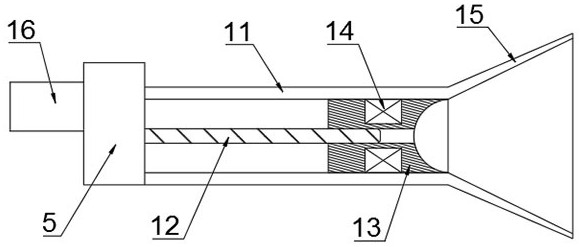
[0060] This embodiment provides a cascade component, such as Figure 1 to Figure 8 As shown, it includes a cascade tube assembly 1 provided on the main machine 5 and a cascade rod assembly 2 provided on the slave machine 6;

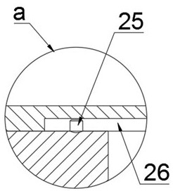
[0061] The cascading tube assembly 1 includes a cascading tube 11, a first screw 12 and an electromagnetic traction column 13, one end of the cascading tube 11 is fixed to the main machine 5, and the other end is open, and the first screw 12 is set In the cascade pipe 11, and arranged along the length direction of the cascade pipe 11, the first screw rod 12 is coaxial with the cascade pipe 11, and the electromagnetic traction column 13 is sleeved on the first screw rod 12. The first screw mandrel 12 can rotate around its own axis, and is used to drive the electromagnetic traction column 13 to move along the length direction of the first screw mandrel 12. The cascade tube 11 also has a first stopper, and the first stopper The device is used to prevent the...

Embodiment 2

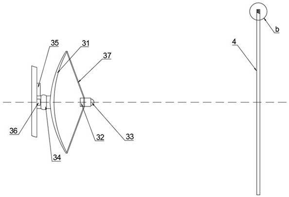
[0070] This embodiment is further optimized on the basis of Embodiment 1, providing an aircraft precise positioning device, such as Figure 9 to Figure 15 As shown, it includes an acoustic wave focusing plate assembly 3 arranged on the master machine 5 and a photoelectric matrix sensor 4 arranged on the slave machine 6;

[0071] The acoustic wave focusing plate assembly 3 includes a focusing plate 31, a pickup 32 and a laser assembly 33, the focusing plate 31 is a parabolic acoustic wave reflection focusing plate 31, the convex surface of the focusing plate 31 is arranged on the main machine 5, the focusing plate 31 notch outer edges are provided with a plurality of support rods 37, and a plurality of said support rods 37 are all connected with the pickup 32, and the working surface of the pickup 32 is positioned at the focal point of the focusing plate 31, and the end of the pickup 32 is located away from the working surface. There is a laser assembly 33, the center of the fo...

Embodiment 3

[0078] This embodiment is further optimized on the basis of Embodiment 3, and provides a positioning method for an aircraft precise positioning device, such as Figure 16 to Figure 20 shown, including the following steps:

[0079] Step 1: When the aircraft needs cascading, the base confirms the cascading parent aircraft 5, and establishes a cascading relationship between the parent aircraft 5 and the slave aircraft 6, and establishes a cascading information transmission link;

[0080] Step 2: After the cascading information transmission link is established, the sub-unit 6 sends real-time audio characteristics to the base unit 5, and the base unit 5 compares it with the surrounding sound source sent by the pickup 32 after receiving it, and judges whether the sub-unit 6 enters the audio guidance range;

[0081]Step 3: When the sub-unit 6 enters the audio guidance range, the main unit 5 controls the focus board 31 to search for the direction of the maximum audio field strength of...


PUM


Abstract

The invention discloses a positioning method for an aircraft precise positioning device, relates to the technical field of unmanned aircraft, and includes a cascade pipe assembly provided on a parent aircraft and a cascade rod assembly provided on a slave aircraft; the cascade pipe assembly includes a cascade pipe assembly , the first screw rod and the electromagnetic traction column; the cascading rod assembly includes a cascading rod, one end of the cascading rod is arranged on the slave machine, and the other end has a permanent magnet ball head, and the cascading rod is arranged along its own axis There is a screw hole for the first screw screw to extend in, and the screw hole runs through the cascade rod and the permanent magnet ball in turn; the end of the electromagnetic traction column has a On the end face, an electromagnetic coil is arranged inside the electromagnetic traction column, and the electromagnetic coil changes magnetic poles for attracting or repelling the permanent magnet ball head. When this scheme is used for cascading, it improves the cascading precision and ensures the safety of the aircraft.

Description

technical field [0001] The invention relates to the technical field of unmanned aerial vehicles, in particular to a positioning method for an aircraft precise positioning device. Background technique [0002] The positioning technology of traditional UAVs in flight mainly comes from satellite positioning and guidance. This technology has been widely used, but it faces poor accuracy when it is applied to application scenarios such as air cascading in motion and high-precision landing. , easy to interfere and other weaknesses, so it is extremely difficult for the aircraft to achieve high-precision positioning. [0003] Therefore, for application scenarios such as aerial cascading in motion and high-precision landing, there is an urgent need for a device that can realize air cascading and precise landing in motion. Contents of the invention [0004] The technical problem to be solved by the present invention is that it is extremely difficult for the aircraft to achieve high-...

Claims


Application Information

Patent Timeline
Patent Type & Authority Patents(China)
IPC IPC(8): B64D47/00
CPCB64D47/00
Inventor 张弓
Owner 四川迅联达智能科技有限公司
Why Eureka
Try Eureka