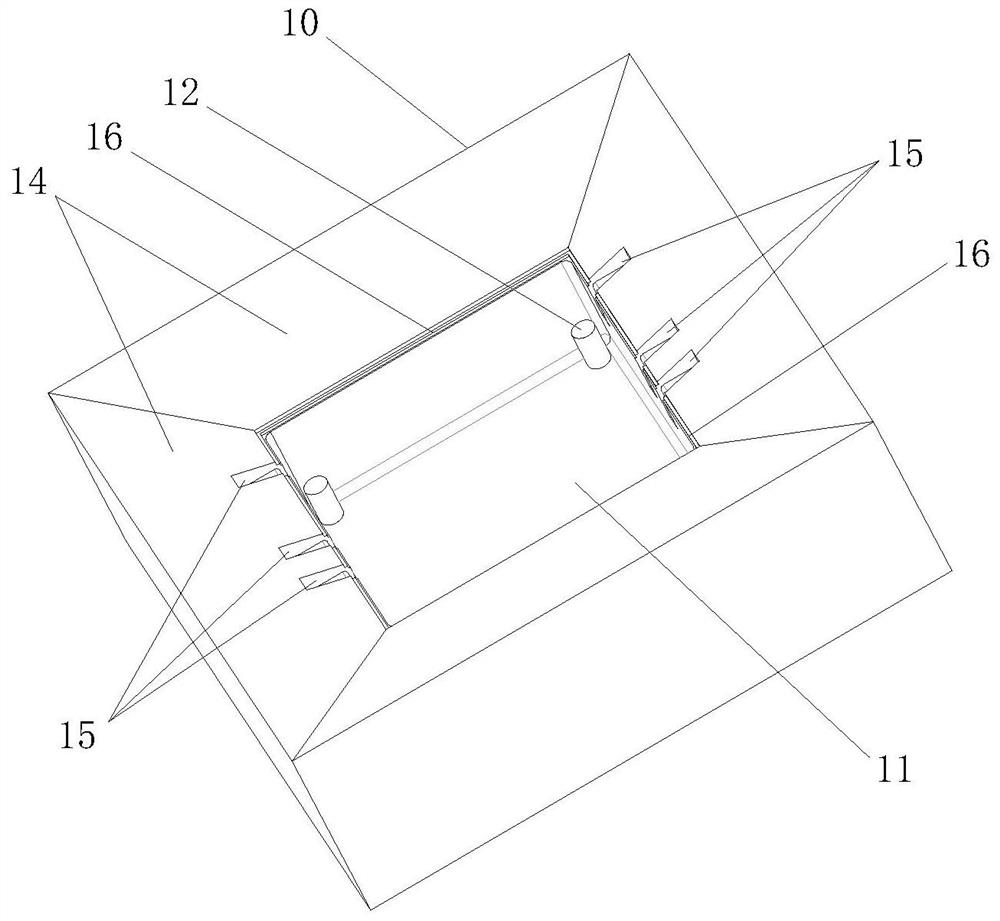
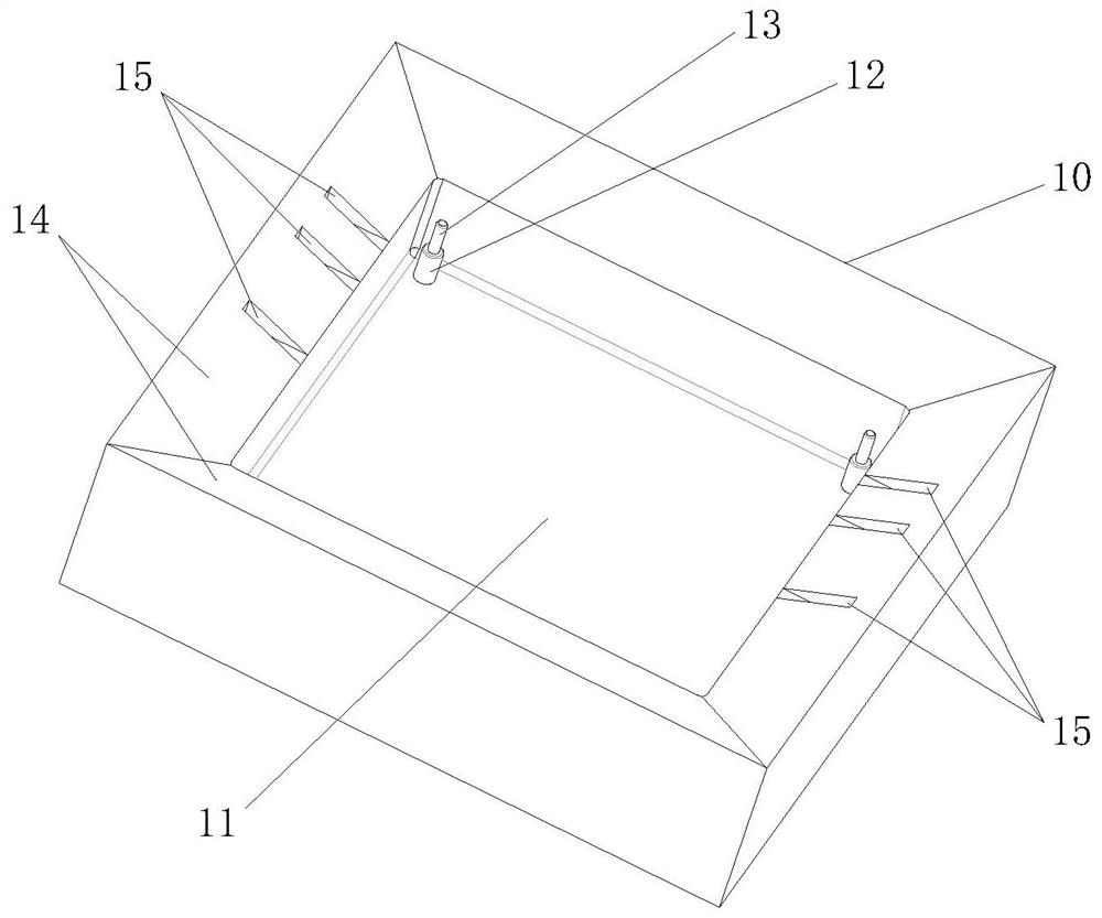
Electronic device packaging mold

A technology of electronic devices and molds, which is applied in the fields of electrical components, encapsulation/impregnation, inductance/transformer/magnet manufacturing, etc. It can solve the problems of unfavorable product development and testing, and achieve the effect of avoiding glue overflow and convenient demoulding

Inactive Publication Date: 2021-11-23
无锡燊旺和电子科技有限公司
View PDF0 Cites 0 Cited by
  • Summary
  • Abstract
  • Description
  • Claims
  • Application Information

AI Technical Summary

Problems solved by technology

Such a long lead time for existing packaging molds is not conducive to product development and testing, which is obviously unacceptable to current chip companies

Method used


Image

  • Electronic device packaging mold
  • Electronic device packaging mold

Examples


Embodiment Construction

[0027] In order to make the above objects, features and advantages of the present invention more comprehensible, specific implementations of the present invention will be described in detail below in conjunction with the accompanying drawings. In the following description, numerous specific details are set forth in order to provide a thorough understanding of the present invention. However, the present invention can be implemented in many other ways different from those described here, and those skilled in the art can make similar improvements without departing from the connotation of the present invention, so the present invention is not limited by the specific embodiments disclosed below.

[0028] It should be noted that when an element is referred to as being “fixed” to another element, it can be directly on the other element or there can also be an intervening element. When an element is referred to as being "connected to" another element, it can be directly connected to t...


PUM

PropertyMeasurementUnit
Heightaaaaaaaaaa

Abstract

The invention discloses an electronic device packaging mold which is used for integrally packaging a winding and a magnetic core assembly and forming a packaging layer on the surface, and a plurality of positioning holes are formed in the winding. The electronic device packaging mold comprises an open mold body, the mold body is provided with a glue injection groove which is sunken downwards, a vertically-arranged supporting column corresponding to the positioning hole is arranged on the bottom face in the glue injection groove, and the size of the cross section of the supporting column is greater than that of the cross section of the positioning hole; and the supporting columns are supported on the surface of the winding where the positioning holes are located. According to the electronic device packaging mold, the supporting columns are connected with the winding positioning holes in an aligned mode, the winding can be controlled to be placed at the proper position, and therefore the packaging size is accurately controlled.

Description

technical field [0001] The invention relates to the technical field of electronic device packaging, in particular to an electronic device packaging mold. Background technique [0002] In the field of electronic devices, some electronic devices need to be packaged before use. For example, in a chip transformer, after the winding and the magnetic core are assembled, in order to fix the winding and the magnetic core, it is necessary to package the assembled winding and the magnetic core as a whole. The conventional packaging method is to customize the packaging mold according to the size of the winding / magnetic core according to the chip industry process. Normally, it takes at least one month to debug the mold, then use the mold for packaging, and then test the overall chip transformer. Such a long lead time for existing packaging molds is not conducive to product development and testing, which is obviously unacceptable to current chip companies. Contents of the invention ...

Claims


Application Information

Patent Timeline
IPC IPC(8): H01F41/00B29C45/26B29C45/14
CPCH01F41/005B29C45/26B29C45/14
Inventor 娄建勇张旭东袁凯姚炜尹玮
Owner 无锡燊旺和电子科技有限公司
Why Eureka
Try Eureka