
Automatic test wiring device for distribution transformer detection

A technology for distribution transformers and automatic testing, applied in the parts of connecting devices, connecting/disconnecting connecting devices, coupling devices, etc., can solve the problems of troublesome manual wiring, low efficiency and low safety, and improve work safety. performance, saving labor costs, and facilitating wiring and disconnecting

Pending Publication Date: 2021-11-23
STATE GRID JIANGSU ELECTRIC POWER CO ELECTRIC POWER RES INST +2
View PDF0 Cites 4 Cited by
  • Summary
  • Abstract
  • Description
  • Claims
  • Application Information

AI Technical Summary

Problems solved by technology

[0002] During the high-voltage electrical test of a distribution transformer with a voltage level of 10kV, it is necessary to wire all the three-phase terminals on the low-voltage side. Since the current on the low-voltage side is above 1000A, manual wiring is more troublesome, the safety is not high, and the efficiency is low. Manual wiring is required. Wiring and disconnecting more than once, the test process requires a lot of manual cooperation, and the test sequence is cumbersome and complicated
Although the current detection station already has a certain test automation detection function, it cannot be separated from the link of manual connection and disconnection, and cannot truly achieve the goal of unmanned batch detection throughout the detection process, which affects the detection efficiency.

Method used


Image

  • Automatic test wiring device for distribution transformer detection

Examples


Embodiment Construction

[0036] The present invention will be further described in detail below in conjunction with the accompanying drawings and embodiments. It should be understood that the specific embodiments described here are only used to explain the present invention, but not to limit the present invention. In addition, it should be noted that, for the convenience of description, only some structures related to the present invention are shown in the drawings but not all structures.

[0037] In the description of the present invention, unless otherwise clearly specified and limited, the terms "connected", "connected" and "fixed" should be understood in a broad sense, for example, it can be a fixed connection, a detachable connection, or an integrated ; It can be a mechanical connection or an electrical connection; it can be a direct connection or an indirect connection through an intermediary, and it can be the internal communication of two components or the interaction relationship between two ...


PUM


Abstract

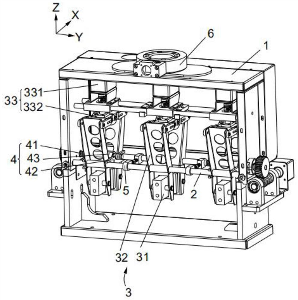
The invention relates to the technical field of distribution transformers, and discloses an automatic test wiring device for distribution transformer detection. The device comprises a support, two installation rods and three switching mechanisms, the two installation rods are movably arranged on the support in parallel, at an interval and along the X-axis direction, and the three switching mechanisms are arranged on the support along the Y-axis direction and at intervals; the two switching mechanisms located at the outer side can move along the Y-axis direction, and each switching mechanism comprises two switching clamping blocks. One switching clamping block is rotationally connected to one installation rod, the other switching clamping block is rotationally connected to the other installation rod, the two switching clamping blocks are oppositely arranged and can be close to or far away from each other so as to clamp or loosen a binding post, and the Y-axis direction is perpendicular to the X-axis direction. The automatic test wiring device for distribution transformer detection saves the wiring time and labor cost, and is higher in wiring safety and efficiency.

Description

technical field [0001] The invention relates to the technical field of distribution transformers, in particular to an automatic test wiring device for detection of distribution transformers. Background technique [0002] During the high-voltage electrical test of a distribution transformer with a voltage level of 10kV, it is necessary to wire all the three-phase terminals on the low-voltage side. Since the current on the low-voltage side is above 1000A, manual wiring is more troublesome, the safety is not high, and the efficiency is low. Manual wiring is required. Wiring and dismantling have been done many times, the test process requires a lot of manual cooperation, and the test sequence is cumbersome and complicated. Although the current testing station already has a certain automatic testing function, it cannot break away from the link of manual connection and disconnection, and cannot truly achieve the goal of unmanned batch testing throughout the testing process, which ...

Claims


Application Information

Patent Timeline
Patent Type & Authority Applications(China)
IPC IPC(8): H01R13/629H01R9/24H01R43/26
CPCH01R13/629H01R9/24H01R43/26
Inventor 戴建卓刘伟贾勇勇陶加贵赵恒张思聪陈昱彤储昭杰周雄伟周宇李炯朱斌胡俊
Owner STATE GRID JIANGSU ELECTRIC POWER CO ELECTRIC POWER RES INST
Learn More