Fault monitoring method, device, equipment and storage medium for optical fiber link

A fiber optic link and fault monitoring technology, which is applied in the direction of testing optical fiber/optical waveguide equipment, measuring devices, optical instrument testing, etc., can solve the problems of low fault monitoring accuracy, data acquisition lag, and low work efficiency, so as to improve work Efficiency and accuracy, and the effect of improving reliability

Active Publication Date: 2022-07-29
GUANGDONG POWER GRID CO LTD +1
View PDF3 Cites 0 Cited by
  • Summary
  • Abstract
  • Description
  • Claims
  • Application Information

AI Technical Summary

Problems solved by technology

[0003] With the large-scale construction and operation of power optical fiber communication networks, the length of power optical cables and the number of optical fibers represented by fully insulated optical unit phase conductors (Insulated Optical Unit Phase Conductor, IOPPC) continue to increase, and the scale of optical fiber distribution systems is increasing. The number of optical fiber link components is large and the connection relationship is complex, which brings many problems such as management and fault monitoring. The specific performance is the lack of fault monitoring technology for optical fiber links, low fault monitoring accuracy and serious data acquisition. Lag and other problems, there is an urgent need for effective intelligent fault monitoring methods to ensure the stable and reliable operation of the power optical fiber communication network
[0004] At present, the existing optical fiber link fault monitoring method is mainly that the operation and maintenance personnel judge the damaged optical fiber components based on experience, manually check the business data transmitted by them to determine the affected services, and notify the operation and maintenance personnel to correct the damaged optical fiber components. Maintenance of damaged optical fiber components, low work efficiency

Method used


Image

  • Fault monitoring method, device, equipment and storage medium for optical fiber link
  • Fault monitoring method, device, equipment and storage medium for optical fiber link
  • Fault monitoring method, device, equipment and storage medium for optical fiber link

Examples


Embodiment 1

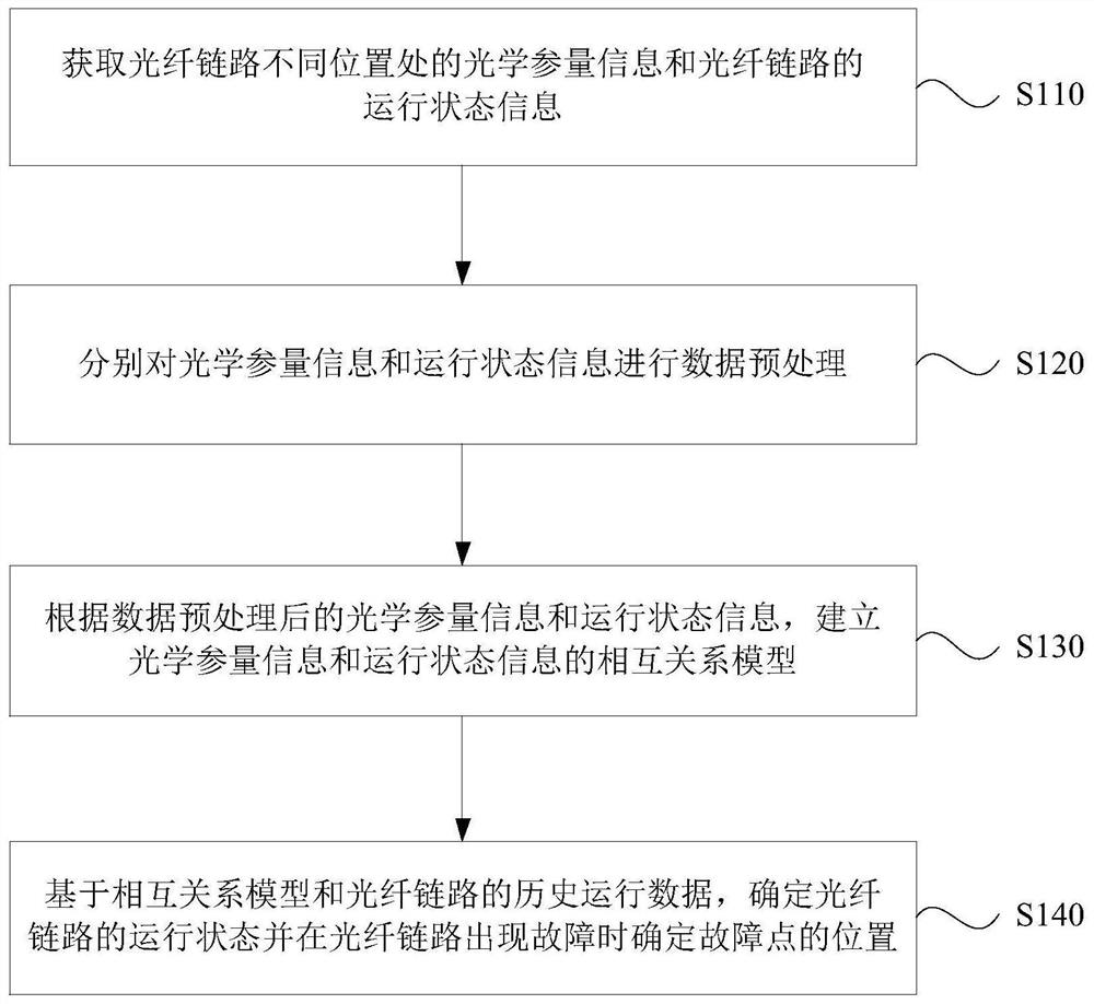
[0048] figure 1 This is a schematic flowchart of a method for monitoring a fault of an optical fiber link provided by the present invention. This embodiment can be applied to the situation of monitoring the fault of an optical fiber link. The method can be executed by a fault monitoring device of the optical fiber link. The device can use Implemented in software and / or hardware, the apparatus can be configured in an electronic device, such as a server or a terminal device. Typical terminal devices include mobile terminals, specifically mobile phones, computers, or tablet computers. like figure 1 As shown, the method may specifically include:

[0049] S110. Acquire optical parameter information and operating status information of the optical fiber link at different positions of the optical fiber link.

[0050]Specifically, the optical fiber links in each embodiment of the present invention may be an optical fiber link based on a fully insulated optical unit composite phase co...

Embodiment 2

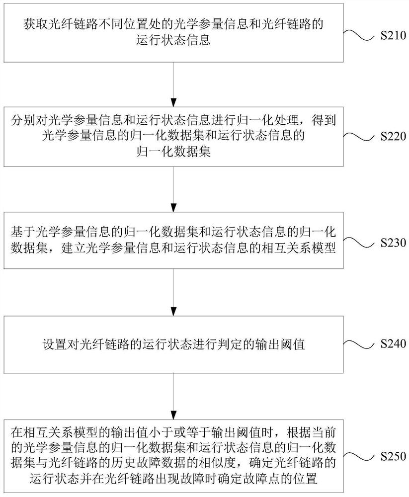
[0062] figure 2 It is a schematic flowchart of another optical fiber link fault monitoring method provided by the present invention. On the basis of the above-mentioned embodiment, this embodiment further optimizes the above-mentioned fault monitoring method of the optical fiber link. like figure 2 As shown, the fault monitoring method of the optical fiber link specifically includes:

[0063] S210. Obtain optical parameter information and operating status information of the optical fiber link at different positions of the optical fiber link.

[0064] S220. Perform normalization processing on the optical parameter information and the operating state information respectively, to obtain a normalized data set of the optical parameter information and a normalized data set of the operating state information.

[0065] Specifically, by normalizing the optical parameter information and the operating state information respectively, it is helpful to map each optical parameter inform...

Embodiment 3

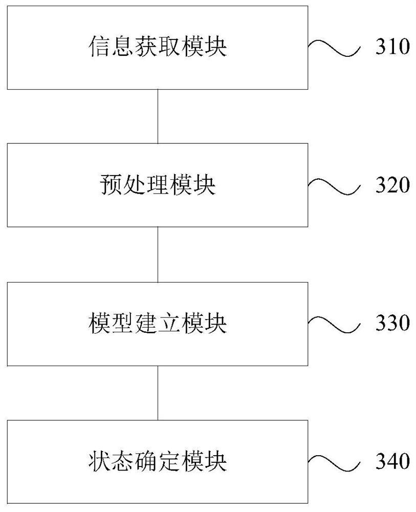
[0092] image 3 It is a schematic diagram of the module structure of a fault monitoring device for an optical fiber link provided by the present invention, and this embodiment can be applied to the situation of fault monitoring of an optical fiber link. The optical fiber link fault monitoring device provided by the present invention can execute the optical fiber link fault monitoring method provided by any embodiment of the present invention, and has functional modules and beneficial effects corresponding to the execution method.

[0093] like image 3 As shown, the device specifically includes an information acquisition module 310, a preprocessing module 320, a model establishment module 330 and a state determination module 340, wherein:

[0094] The information acquisition module 310 is configured to acquire optical parameter information at different positions of the optical fiber link and operating status information of the optical fiber link;

[0095] The preprocessing m...


PUM


Abstract

The invention discloses a fault monitoring method, device, equipment and storage medium for an optical fiber link. The fault monitoring method of the optical fiber link includes: obtaining the optical parameter information at different positions of the optical fiber link and the operating state information of the optical fiber link; respectively performing data preprocessing on the optical parameter information and the operating state information; Parameter information and operating state information, establish a relationship model between optical parameter information and operating state information; based on the relationship model and the historical operating data of the optical fiber link, determine the operating state of the optical fiber link and determine the fault when the optical fiber link fails point location. The technical scheme of the present invention realizes real-time monitoring and automatic fault diagnosis of the operation state of the optical fiber link, which helps to improve the working efficiency and accuracy of the fault monitoring of the optical fiber link, thereby improving the reliability of the optical fiber link components.

Description

technical field [0001] The present invention relates to the technical field of power optical fiber communication, and in particular, to a fault monitoring method, device, equipment and storage medium for an optical fiber link. Background technique [0002] In recent years, optical fiber communication has played an important role in the fields of power dispatching, distribution network automation and relay protection, and is the basis for ensuring dynamic regulation and stable operation of the power grid. The power optical fiber communication network is mainly composed of optical fiber jumpers, optical fiber wiring and optical cables and other components, as well as transmission and switching equipment. Its reliability, real-time and stability are directly related to the stability and operational benefits of the power grid. [0003] With the large-scale construction and operation of power optical fiber communication networks, the length of power optical cables and the number ...

Claims


Application Information

Patent Timeline
Patent Type & Authority Patents(China)
IPC IPC(8): H04B10/079G06F30/18G01M11/00
CPCH04B10/0791G06F30/18G01M11/30
Inventor 钟超逸骆宇平王曦彤郑兴月张璐娟雷雨周文曾夏叶谭翠容黄青平何溢叶明武陈丽光邹晓明
Owner GUANGDONG POWER GRID CO LTD
Why Eureka
Try Eureka