Locking prosthesis for ankle joint

An ankle joint and prosthesis technology, applied in the medical field, can solve problems such as complicated installation and difficult revision, and achieve the effect of reducing the amount of osteotomy, convenient connection, and good ankle joint movement

Pending Publication Date: 2021-11-26
BEIJING CHUNLIZHENGDA MEDICAL INSTR
View PDF7 Cites 0 Cited by
  • Summary
  • Abstract
  • Description
  • Claims
  • Application Information

AI Technical Summary

Problems solved by technology

Although this combination is stable, it is complicated to install and difficult to repair later.

Method used


Image

  • Locking prosthesis for ankle joint
  • Locking prosthesis for ankle joint
  • Locking prosthesis for ankle joint

Examples


Embodiment Construction

[0023] The preferred embodiments of the present invention will be described below in conjunction with the accompanying drawings. It should be understood that the preferred embodiments described here are only used to illustrate and explain the present invention, and are not intended to limit the present invention.

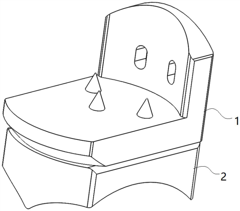
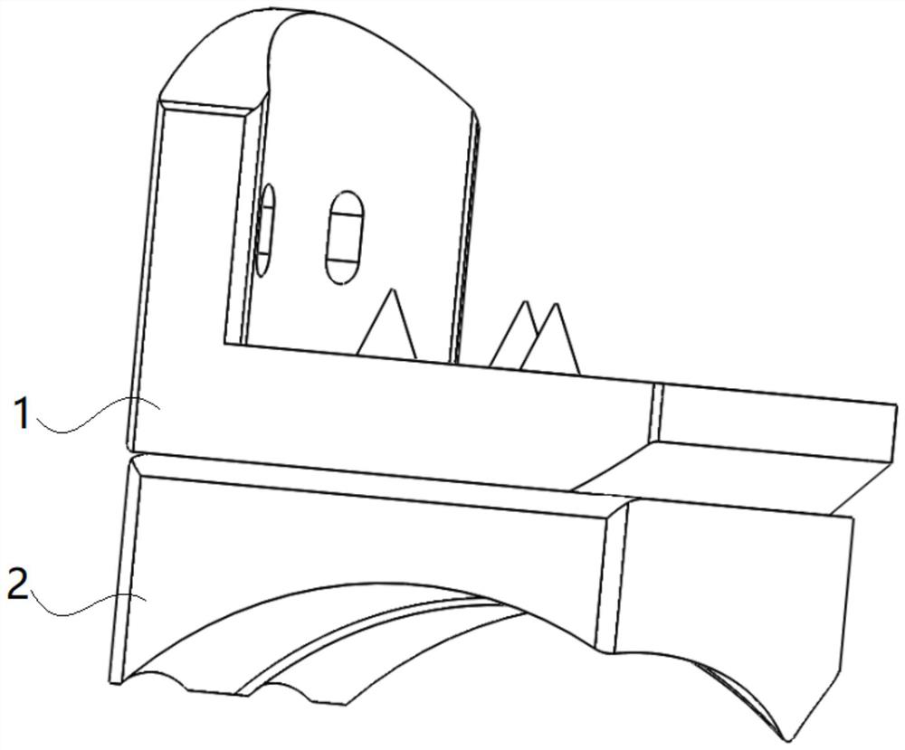
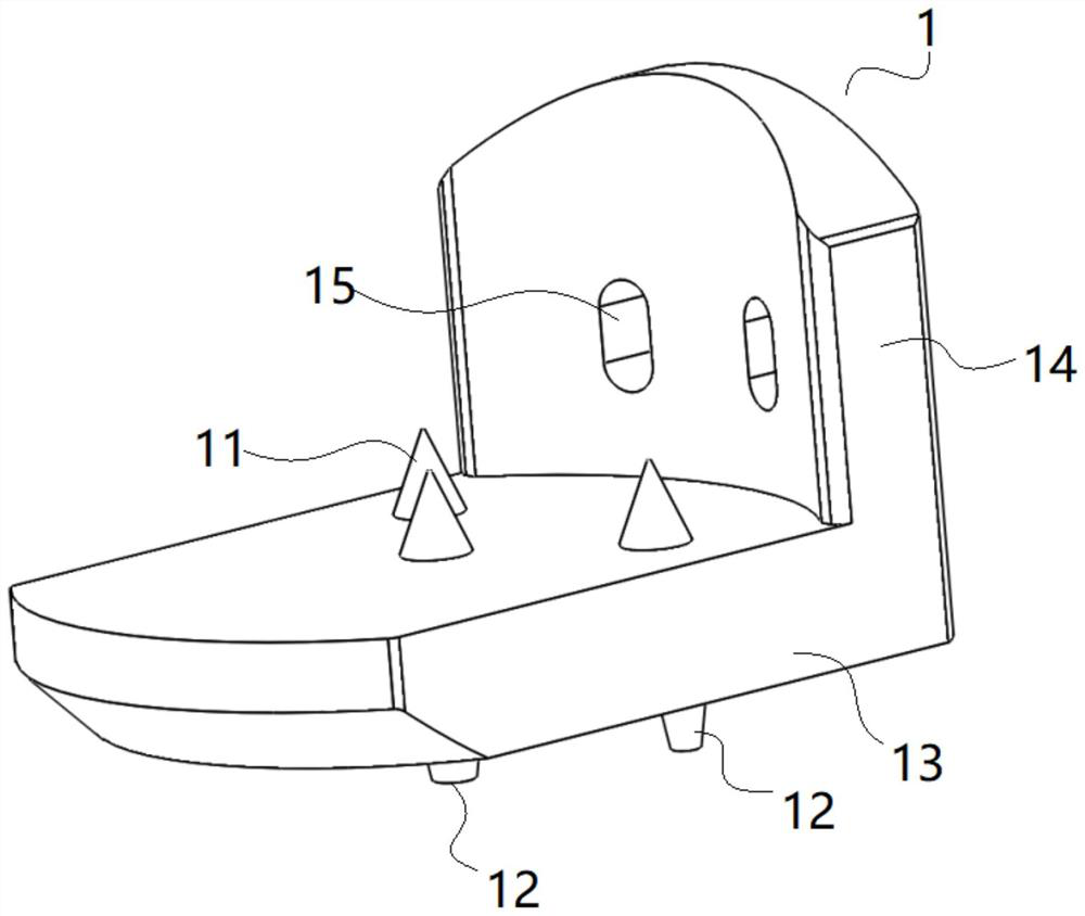
[0024] In order to overcome the technical problems of poor stability and inconvenient revision of the ankle prosthesis in the prior art, the present invention provides a locking prosthesis for the ankle joint, according to Figure 1-Figure 8 shown, including:

[0025] The tibial support body 1 is provided with a cone 11 for fixed connection with the tibial end, and a cone column 12 corresponding to the cone 11, and the cone column 12 and the cone 11 are arranged on the tibia The position of the tray body 1 is opposite; the tibial tray body 1 adopts an integrated structure design, which reduces operation steps and improves operation efficiency.

[0026] The tibial p...


PUM


Abstract

The invention provides a locking prosthesis for an ankle joint. The locking prosthesis for the ankle joint comprises a tibia support body, on which a cone fixedly connected with a tibia end and a cone column corresponding to the cone are arranged, and the cone column and the cone are opposite in position on the tibia support body; a tibia liner is provided with a conical matching hole matched with the conical column, and is used for being inserted into the conical matching hole to connect the tibia support body with the tibia liner. The locking prosthesis for the ankle joint has the advantages that the structure of the prosthesis can be used in an ankle joint replacement prosthesis after being connected with a talus apex prosthesis, the connection is convenient, and more possibilities can be provided for later revision while the stable combination of the tibia support body and the tibia liner is ensured; and the lower end of the tibia liner adopts a curved surface design adaptive to a bionic talus arc, so that the ankle joint movement can be better simulated while the orthogonality of the prosthesis is ensured.

Description

technical field [0001] The invention relates to the field of medical technology, in particular to a locking prosthesis for ankle joints. Background technique [0002] At present, in ankle joint replacement surgery, most of the replacement prostheses used on the tibial side are fixed by the tibial stem. For example, the INBONE II ankle joint replacement prosthesis is fixed on the tibial side. The method of fixation with the tibial stem, although this fixation method can play a fixed role, but the stability is poor, the operation is complicated, and the operation effect is average. At the same time, most of the combination of the tibial tray and the liner adopts a dovetail-type combination method, and is locked with a reverse bevel. Although this combination method is stable, it is complicated to install and difficult to repair later. Therefore, it is necessary to design a replacement prosthesis with stable tibial fixation, convenient installation, and simple revision, which...

Claims


Application Information

Patent Timeline
Patent Type & Authority Applications(China)
IPC IPC(8): A61F2/42
CPCA61F2/4202
Inventor 朱海阔史春宝郭静王振国朱更博
Owner BEIJING CHUNLIZHENGDA MEDICAL INSTR
Why Eureka
Try Eureka