Reinforcing bar engineering waste recycling device

A technology of waste recycling and steel bar engineering, applied in the direction of grain processing, etc., can solve the problems of insufficient separation of cement blocks, waste of manpower, low efficiency, etc., and achieve the effect of convenient unified collection, secondary recycling, and thorough separation

Inactive Publication Date: 2021-11-26
DEZHOU VOCATIONAL & TECHN COLLEGE
View PDF0 Cites 0 Cited by
  • Summary
  • Abstract
  • Description
  • Claims
  • Application Information

AI Technical Summary

Problems solved by technology

[0002] Common solid wastes on the construction site of construction projects mainly include: construction slag and discarded bulk building materials, construction slag usually includes bricks, gravel, slag, concrete fragments, scrap steel, broken glass, waste chips and waste Decorative materials, etc.; waste bulk building materials usually include cement and lime, etc. Due to the high cost of steel bars, waste steel bars are usually recycled in construction projects, but mo

Method used


Image

  • Reinforcing bar engineering waste recycling device
  • Reinforcing bar engineering waste recycling device
  • Reinforcing bar engineering waste recycling device

Examples


Embodiment 1

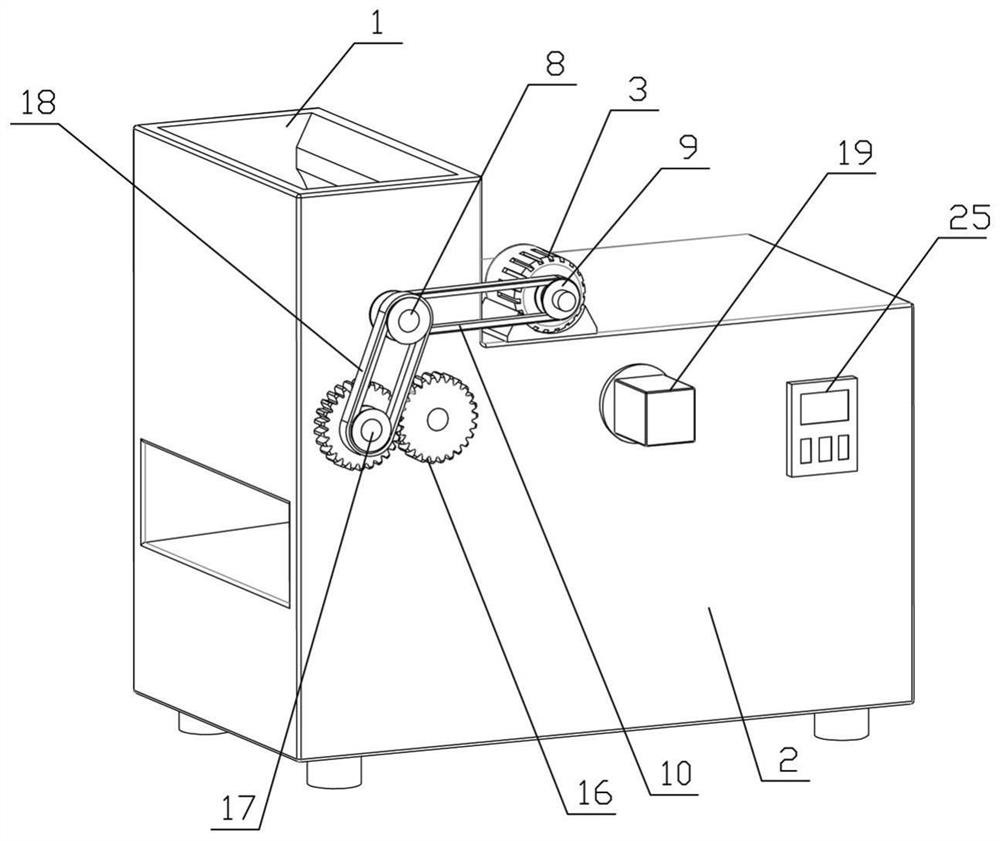
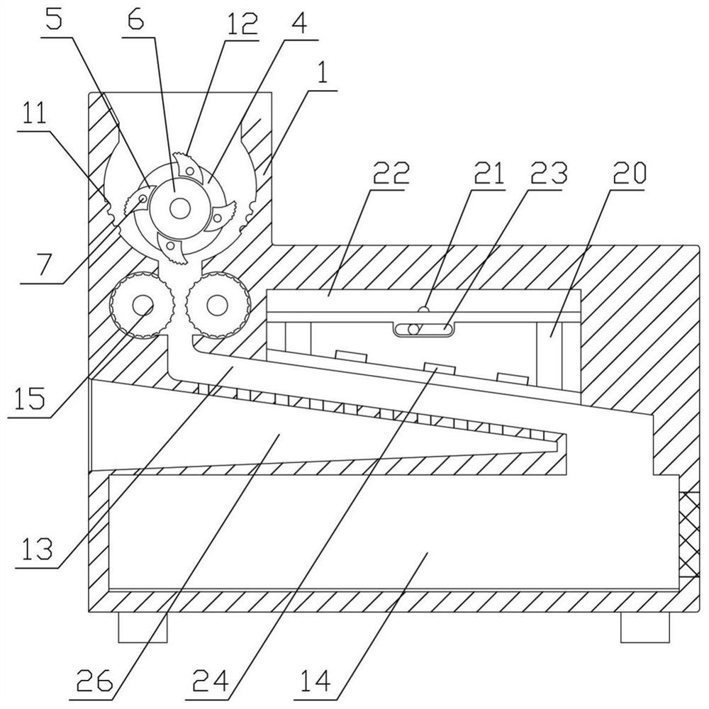
[0024] see Figure 1-2 , the present embodiment provides a technical solution: a steel engineering waste recycling device, including a hopper 1, a housing 2 and a first drive motor 3;

[0025] The inside of the hopper 1 is provided with a first crushing mechanism, the first crushing mechanism includes a knife seat 4 and a plurality of crushing knives 5 evenly distributed on the sides of the knife seat 4, the knife seat 4 is assembled and connected with the hopper 1 through the installation shaft 6, and the knife seat 4 The outer side is provided with an annular groove, and the crushing knife 5 is installed in the annular groove by a fixed shaft 7. The end of the installation shaft 6 is provided with a double-groove pulley 8, and the output shaft of the first drive motor 3 is provided with a second pulley 9, and the second pulley 9 It is connected with the double-groove pulley 8 through the transmission of the second belt 10. The inner wall of the hopper 1 is symmetrically pro...

Embodiment 2

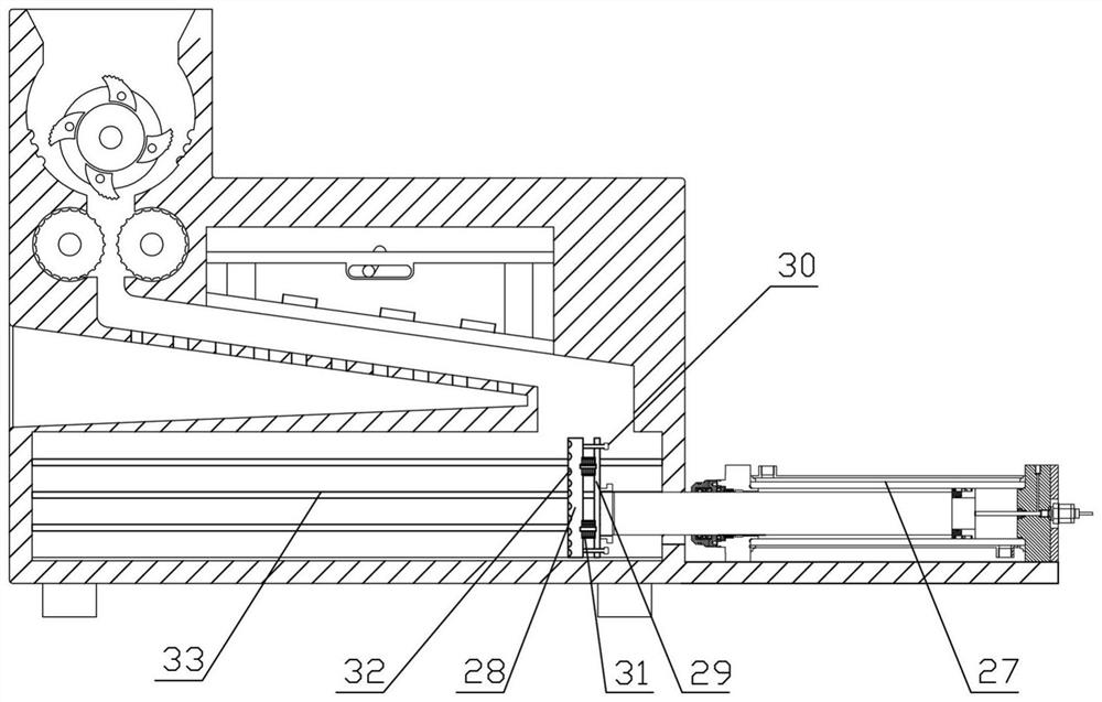
[0035] The structure of this embodiment is basically the same as that of Embodiment 1, the difference is: as image 3 As shown, a steel bar extruding mechanism is set on the housing 2, and the steel bar extruding tool includes a hydraulic cylinder 27 and a pressing plate 28, the cylinder body of the hydraulic cylinder 27 is fixedly connected with the housing 2, and the piston rod of the hydraulic cylinder 27 extends into the collection chamber The inner rear is fixedly connected with an end plate 29, and the pressing plate 28 is assembled on the end plate 29 through four positioning columns 30, one end of the positioning column 30 is fixedly connected with the pressing plate, and the other end of the positioning column 30 penetrates the end plate 29 to set a limit block, Limiting block adopts the metal block that is welded on the positioning post 30 or the nut that is threadedly connected on the positioning post 30 all can, disc spring group 31 is set between pressing plate 28 ...


PUM


Abstract

The invention discloses a reinforcing bar engineering waste recycling device. The reinforcing bar engineering waste recycling device comprises a hopper (1), a shell (2) and a first driving motor (3); a first crushing mechanism is arranged in the hopper (1); and a sliding way (13), a collecting cavity (14), a second crushing mechanism and a third crushing mechanism are arranged in the shell (2), the sliding way (13) is obliquely arranged, and the two ends of the sliding way (13) communicate with the hopper (1) and the collecting cavity (14) correspondingly. By means of the device, cement blocks on the outer sides of reinforcing bars can be crushed in a multi-stage manner, crushing is more thorough, the reinforcing bars and the cement blocks are separated more thoroughly, and unified collection and secondary recycling of the reinforcing bars are convenient.

Description

technical field [0001] The invention relates to the technical field of engineering waste recycling, in particular to a recycling device for steel bar engineering waste. Background technique [0002] Common solid wastes on the construction site of construction projects mainly include: construction slag and discarded bulk building materials, construction slag usually includes bricks, gravel, slag, concrete fragments, scrap steel, broken glass, waste chips and waste Decorative materials, etc.; waste bulk building materials usually include cement and lime, etc. Due to the high cost of steel bars, waste steel bars are usually recycled in construction projects, but most of the waste steel bars in construction projects are wrapped outside There are cement blocks, which are not easy to recycle. Most of the workers use tools to knock off the cement blocks and sundries outside the steel bars, and then collect and process the steel bars, resulting in a waste of manpower and low efficie...

Claims


Application Information

Patent Timeline
IPC IPC(8): B02C21/00B02C18/14B02C18/16B02C18/18B02C18/24B02C4/02B02C4/42B02C1/14B02C19/16B02C23/16
CPCB02C21/00B02C18/0084B02C18/14B02C18/16B02C18/18B02C18/24B02C4/02B02C4/42B02C1/14B02C19/16B02C23/16B02C2018/162B02C2201/02B02C2023/165
Inventor 姚玲云赵晓静曹越
Owner DEZHOU VOCATIONAL & TECHN COLLEGE
Why Eureka
Try Eureka