
Accessory machining roller polishing machine convenient to adjust

A technology of drum polishing and accessories, which is applied to surface polishing machine tools, machine tools suitable for grinding the edge of workpieces, metal processing equipment, etc. It can solve the problems of affecting processing efficiency, disorderly placement of bases, and taking up too much time. To achieve the effect of improving processing efficiency

Inactive Publication Date: 2021-11-26
江苏旭泽流体设备有限公司
View PDF0 Cites 0 Cited by
  • Summary
  • Abstract
  • Description
  • Claims
  • Application Information

AI Technical Summary

Problems solved by technology

[0003] In the process of realizing the present invention, the inventor found that the following problems in the prior art have not been solved: 1. The existing polishing treatment site is equipped with multiple groups of polishing machines, and since the processing cylinder and the base with transmission function are detachable, When cleaning the processing cylinders, the bases are often placed randomly. Whenever the bases are used, due to the different batches or specifications of the polishing machine, it is necessary to hold the processing cylinders in many bases and try to see if they can be locked at different distances. The base of the roller, this phenomenon is caused by the inability to adjust the distance between the transmission rings of the processing cylinder. This process takes too much time and indirectly affects the processing efficiency;
[0004] 2. The processing cylinder of the existing polishing machine is mostly exposed on the side wall and cooperates with the cover plate to supply the feeding and discharging and clean the inner wall of the cylinder. This method can only be cleaned by a single person to clean the inner wall of the barrel, although there are idle personnel in the post It is also unable to help clean up, and the exposure is too small to affect the speed of feeding and discharging, and the use effect is not ideal, etc.

Method used


Image

  • Accessory machining roller polishing machine convenient to adjust
  • Accessory machining roller polishing machine convenient to adjust
  • Accessory machining roller polishing machine convenient to adjust

Examples


Embodiment Construction

[0026] In order to make the technical means, creative features, goals and effects achieved by the present invention easy to understand, the present invention will be further described below in conjunction with specific embodiments.

[0027] In describing the present invention, it should be understood that the terms "upper", "lower", "front", "rear", "left", "right", "top", "bottom", "inner", " The orientation or positional relationship indicated by "outside", etc. is based on the orientation or positional relationship shown in the drawings, and is only for the convenience of describing the present invention and simplifying the description, rather than indicating or implying that the referred device or element must have a specific orientation, so as to Specific orientation configuration and operation, therefore can not be construed as limiting the present invention; in the description of the present invention, it should be noted that, unless otherwise clearly specified and limit...


PUM


Abstract

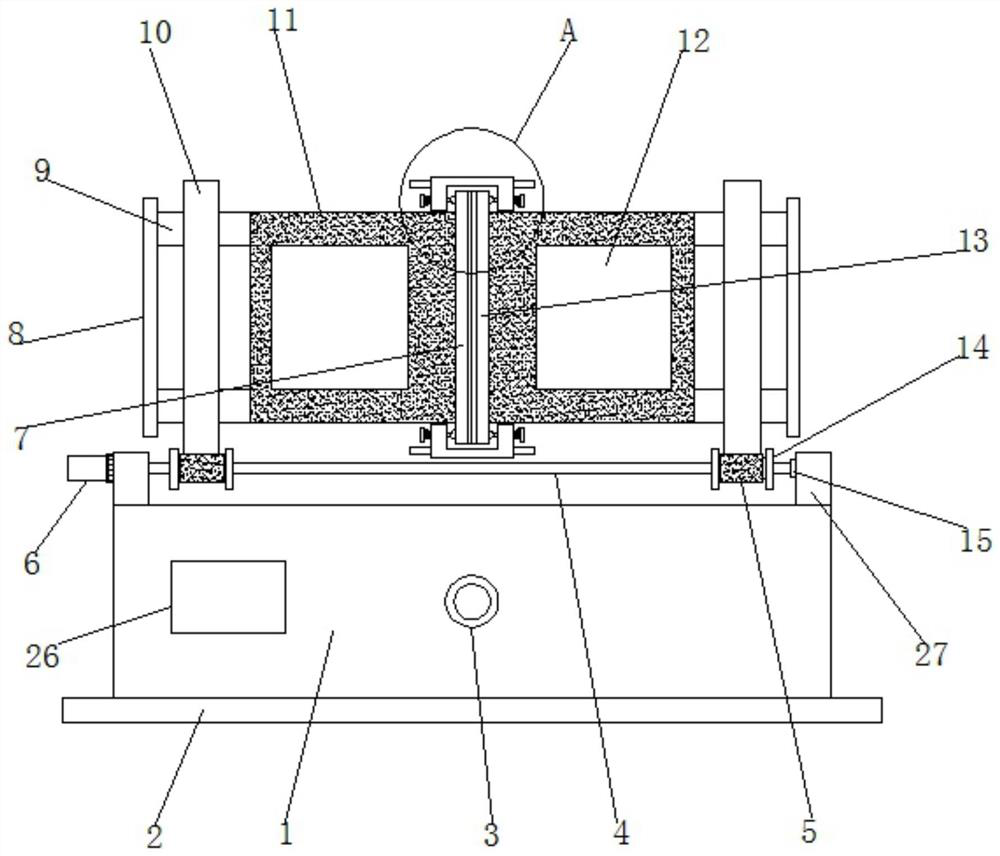
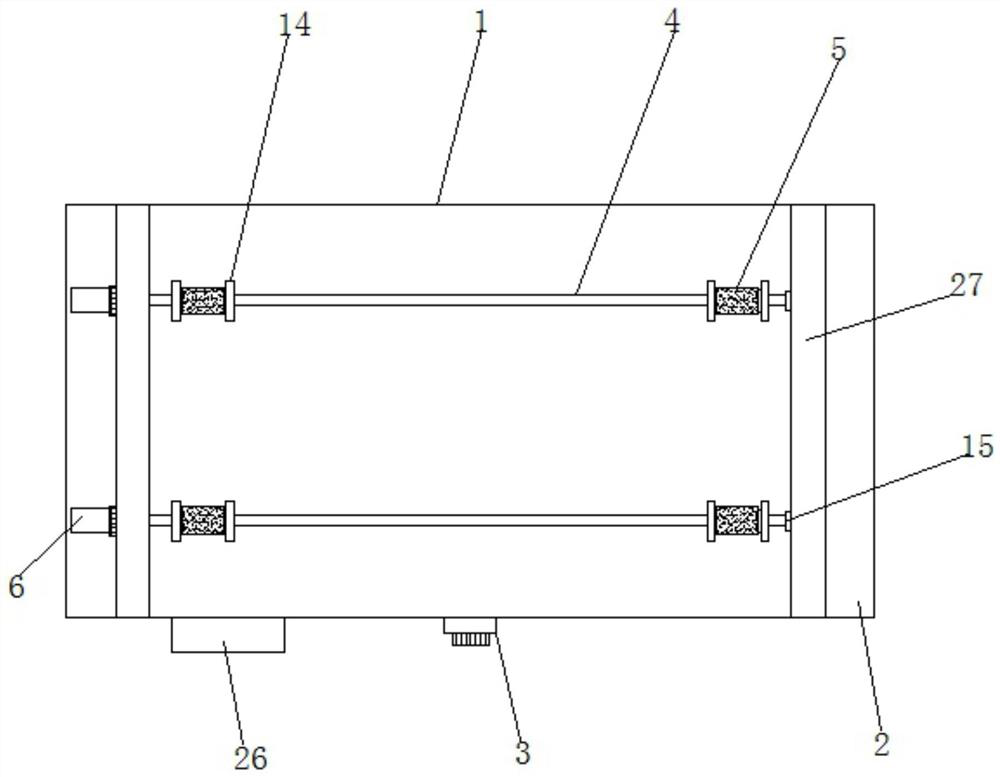
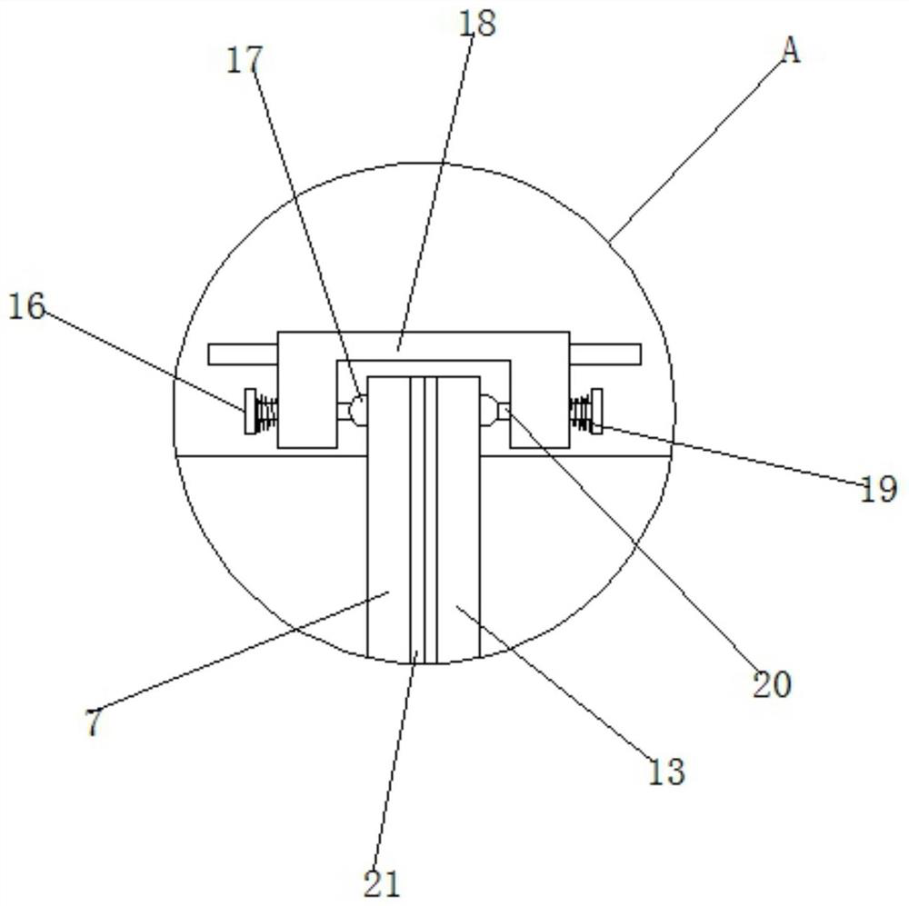
The invention relates to the technical field of grinding and polishing, and discloses an accessory machining roller polishing machine convenient to adjust. The accessory machining roller polishing machine convenient to adjust comprises a base, supporting plates are fixedly mounted on the left and right sides of the top of the base, motors are fixedly mounted on the front and rear sides of the outer wall of the supporting plate on the left side of the top of the base, and a speed adjusting knob is fixedly mounted in the middle of the front wall of the base. The signal output end of the speed adjusting knob is connected with the signal input ends of the motors, the right sides of transmission shafts of the motors are in transmission connection with rotating rods, four groups of transmission rollers are fixedly mounted on the left sides and the right sides of the rotating rods, and a transmission ring is placed between every two adjacent groups of transmission rollers. According to the accessory machining roller polishing machine convenient to adjust, through the arrangement of the transmission rings, hexagonal grooves and hexagonal surfaces, the transmission rings have the adjustable characteristic so as to be matched with the base provided with the transmission rollers at different intervals, a machining barrel has universality, a matched base does not need to be selected from multiple bases, and the machining efficiency is indirectly improved.

Description

technical field [0001] The invention relates to the technical field of grinding and polishing, in particular to an easily adjustable roller polishing machine for processing accessories. Background technique [0002] At present, polishing refers to the use of mechanical, chemical or electrochemical effects to reduce the surface roughness of the workpiece to obtain a bright and flat surface. The finishing machine, also known as the polishing machine, performs surface treatment such as polishing and deburring on the workpiece. Polishing machines mainly include mobile polishing machines, centrifugal polishing machines, and drum polishing machines, which are mostly used for polishing small workpieces. [0003] In the process of realizing the present invention, the inventor found that the following problems in the prior art have not been solved: 1. The existing polishing treatment site is equipped with multiple groups of polishing machines, and since the processing cylinder and th...

Claims


Application Information

Patent Timeline
Patent Type & Authority Applications(China)
IPC IPC(8): B24B31/02B24B31/12B24B41/02B24B47/00
CPCB24B31/02B24B31/12B24B41/02B24B47/00
Inventor 彭志良居爱兵
Owner 江苏旭泽流体设备有限公司
Learn More