Feeding mechanism of edge covering die

A material feeding and mold technology, applied in the field of hemming mold feeding mechanism, can solve the problems of long motion stroke, long motion track, difficult operation, etc., achieve high feeding accuracy, reduce work burden, and improve pass rate.

Pending Publication Date: 2021-11-26
QINHUANGDAO FANGHUA SECM MACHINERY
View PDF0 Cites 0 Cited by
  • Summary
  • Abstract
  • Description
  • Claims
  • Application Information

AI Technical Summary

Problems solved by technology

[0003] The disadvantage of this feeding method is that the movement of the sliver in the injection cavity of the cavity part is long, and there is a compression area of ​​the sliver on the cavity part, the cavity part of the mold convex core is in a closed environment, and there are cavity parts around it. cooperate with it
As a result, when the sliver is loaded, there are obstacles all around, which makes the sliver feeding mechanism complicated and difficult to operate.
Manual feeding is laborious and increases the work intensity of the operator. Due to the long trajectory of oil cylinder feeding, it is easy to cause misalignment of lip feeding
In this process, because the sliver is long, it has a radian, and there are two lips on the side of the sliver, it needs to be placed correctly. The impact is that the operator needs to practice the feeding technique repeatedly, be careful and meticulous, and have high-intensity labor intensity to put the sliver. The feeding work is done well, which greatly increases the operator's load and the probability of defective products

Method used


Image

  • Feeding mechanism of edge covering die
  • Feeding mechanism of edge covering die

Examples


Embodiment Construction

[0017] Below in conjunction with accompanying drawing and embodiment the present invention will be further described:

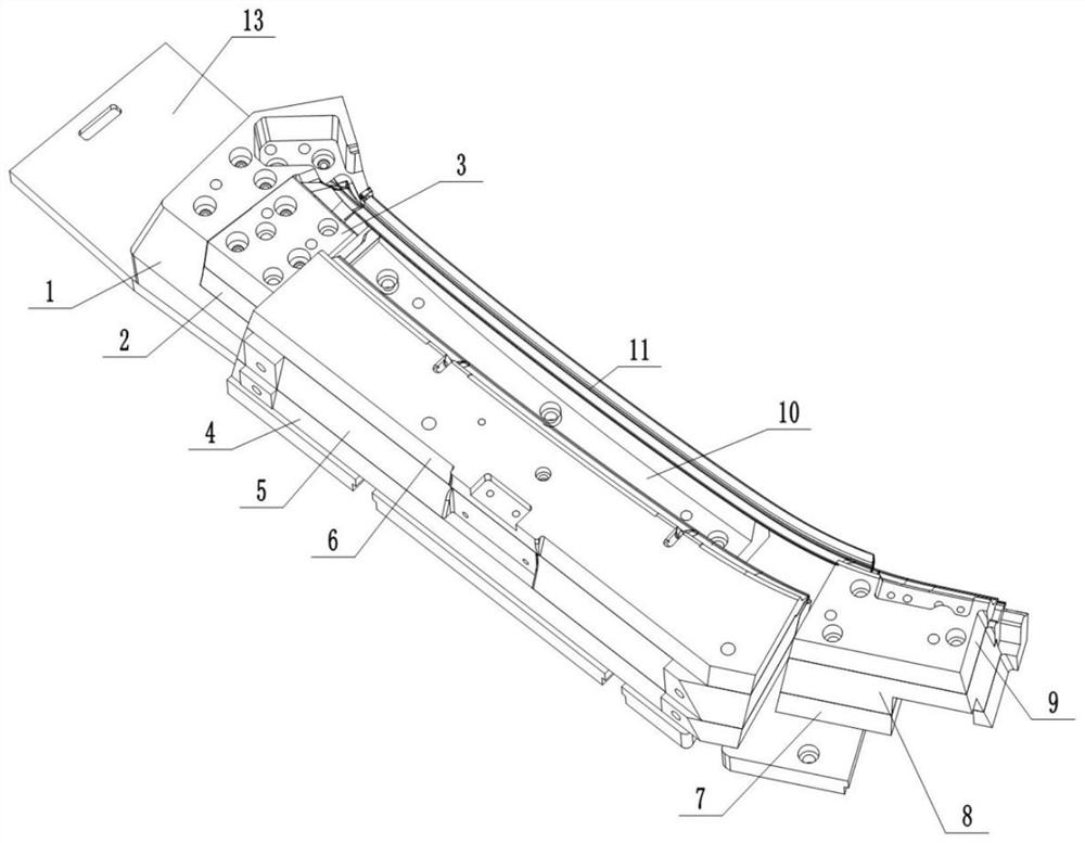
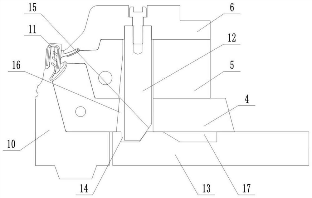
[0018] Such as Figure 1 to Figure 2 As shown, a feeding mechanism for the hemming mold includes a first end feeding assembly, an intermediate feeding assembly, a second end feeding assembly and a bottom plate 13, and the intermediate feeding assembly is located between the first end feeding assembly and the first end feeding assembly. Between the second end feeding components, the injection cavity of the first end feeding component, the middle feeding component and the second end feeding component are connected as a whole, the first end feeding component, the middle feeding The feed assembly and the second end feed assembly are installed on the base plate 13;

[0019] The intermediate feeding assembly includes the No. 4 cavity part 4 slidingly connected to the top surface of the bottom plate 13 and the No. 10 cavity part 10 fixed on the bottom plate 13. The...


PUM


Abstract

The invention relates to a feeding mechanism of an edge covering die. The feeding mechanism comprises a first end feeding assembly, a middle feeding assembly, a second end feeding assembly and a bottom plate, the middle feeding assembly is located between the first end feeding assembly and the second end feeding assembly, injection molding cavities of the first end feeding assembly, the middle feeding assembly and the second end feeding assembly are connected into a whole, and the first end feeding assembly, the middle feeding assembly and the second end feeding assembly are installed on the bottom plate. The movement stroke of strips in the injection molding cavities of cavity pieces is shortened, friction between the strips and the cavity pieces can be reduced by shortening the movement stroke of the strips, so that the strips are easily fed, and the feeding accuracy of lip edges of the strips is higher; and the first end feeding assembly and the middle feeding assembly (except the tenth cavity piece) can be far away from the feeding area of the strips, blocking during strip feeding is reduced, strip feeding is easier, the workload of an operator is relieved, and meanwhile the percent of pass of products is increased.

Description

technical field [0001] The invention relates to the technical field of hemming molds, in particular to a feeding mechanism for hemming molds. Background technique [0002] The products processed by the feeding mechanism of the edge-wrapping mold are edge-wrapping door and window seals with strips, which are completed by injection molding of the corner-joint mold. The finished sliver is wrapped by injection rubber as a whole, and its surroundings are all injection molded rubber core parts during the feeding process. When feeding, the inner steel frame of the sliver needs to be inserted into the outwardly moving cavity of the mold. Because the sliver is in a closed environment, the conventional feeding mechanism is that all the core parts supporting the sliver are separated from the core parts that are matched with it, and the distance moved outward is generally greater than the length of the sliver to meet the feeding requirements. When space is required for manual operation...

Claims


Application Information

Patent Timeline
Patent Type & Authority Applications(China)
IPC IPC(8): B29C45/14B29C45/40
CPCB29C45/14008B29C45/40B29C2045/4063
Inventor 不公告发明人
Owner QINHUANGDAO FANGHUA SECM MACHINERY
Why Eureka
Try Eureka