An anti-extrusion storage device for PLA straw transportation
A storage device and anti-extrusion technology, which is applied in the directions of transportation and packaging, packaging, biological packaging, etc., can solve the problems of poor anti-extrusion performance, resource consumption, and weak box covers, so as to improve anti-extrusion performance and reduce The probability of being flattened and the effect of being easy to reset outwards
- Summary
- Abstract
- Description
- Claims
- Application Information
AI Technical Summary
Problems solved by technology
Method used
Image
Examples
Embodiment 1
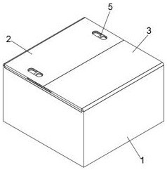
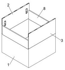
[0030] see figure 1 , figure 2 , image 3 , Figure 4As shown, an anti-extrusion storage device for transporting PLA straws includes a storage box main body 1, and two support box covers 8 are symmetrically arranged on the storage box main body 1, and the two support box covers 8 are symmetrically arranged front and back, and two The support case covers 8 are all located under the No. 1 protection case cover 2 and the No. 2 protection case cover 3, and a No. 1 protection case cover 2 and a No. 2 protection case cover 3 are arranged on the storage box main body 1, and the No. 1 protection case cover 2 and a No. 2 protection box cover 3 are left and right symmetrically arranged, and the inside above the No. 1 protection box cover 2 is provided with a device storage groove 9, and the device storage groove 9 penetrates the front and rear ends of the No. 1 protection box cover 2, and the No. 1 protection box cover The right end of box cover 2 is evenly provided with five telesc...
Embodiment 2
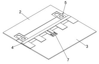
[0032] see figure 2 , image 3 , Figure 5 As shown, a reinforcing device 4 is installed inside the top of the No. 1 protective box cover 2, and the reinforcing device 4 can slide left or right in the No. 1 protective box cover 2. The reinforcing device 4 includes a connecting base plate 15 and a strengthening support plate 16 , there are four strengthening support plates 16 and they are arranged symmetrically on the right end of the connecting base plate 15. The connecting base plate 15 on the strengthening device 4 is installed in the device receiving groove 9 opened in the No. 1 protective box cover 2, and the four strengthening supporting plates 16 are respectively Located in the four telescopic slots 10 on the outside, the reinforced support plate 16 is fixedly installed on the connecting base plate 15 by screws, the left end of the connecting base plate 15 is provided with a No. 1 moving slot 17, and the right end of the connecting base plate 15 is provided with a No. ...
Embodiment 3
[0034] see figure 1 , figure 2 , image 3 , Image 6 , Figure 7 , Figure 8 As shown, two fixing devices 5 are symmetrically installed on the connecting substrate 15. The fixing device 5 includes a connecting base bar 19, a pulling block 20, a connecting baffle 22 and a fixing clamp 23. The pulling block 20 is arranged on the left end of the connecting base bar 19. , the connection baffle 22 is arranged on the inner end of the connection base bar 19, the fixed clamp 23 is arranged on the right end of the connection baffle 22, and the two connection base bars 19 on the two fixing devices 5 are all located at the left end of the connection base plate 15. In the No. moving groove 17, a finger jack 21 is provided on the two pulling blocks 20, and the finger jack 21 penetrates the upper and lower ends of the pulling block 20, and the two connecting baffles 22 are located at the two openings on the right end of the connecting substrate 15. In the No. moving groove 18, two fix...
PUM
 Abstract
Description
Claims
Application Information
 - R&D
- Intellectual Property
- Life Sciences
- Materials
- Tech Scout
- Unparalleled Data Quality
- Higher Quality Content
- 60% Fewer Hallucinations
Browse by: Latest US Patents, China's latest patents, Technical Efficacy Thesaurus, Application Domain, Technology Topic, Popular Technical Reports.
© 2025 PatSnap. All rights reserved.Legal|Privacy policy|Modern Slavery Act Transparency Statement|Sitemap|About US| Contact US: help@patsnap.com


