Dehairing machine capable of reserving position of wire box

A technology of shaving machine and wire box, which is applied in the field of shaving machines, can solve the problems of shaving processing, the inability to reserve shaving positions, and the inability to fully cover the wall, etc., and achieve a high practical effect

Active Publication Date: 2021-11-26
山东林坔幕墙装饰有限公司
View PDF7 Cites 0 Cited by
  • Summary
  • Abstract
  • Description
  • Claims
  • Application Information

AI Technical Summary

Problems solved by technology

[0004] Based on this, it is necessary to address the above problems, to propose a method that can automatically spray water on the wall in advance, can fully shave the wall, and can automatically reserve the wire box according to the position and size of the wire box during the shaving process. The shaving machine can reserve the position of the wire box at the shaving position to solve the problems in the above-mentioned background technology that it cannot automatically spray water on the wall in advance, cannot fully shave the wall, and cannot automatically shave the wall. The problem of reserving the shaving position according to the position and size of the wire box during the hairing process

Method used


Image

  • Dehairing machine capable of reserving position of wire box
  • Dehairing machine capable of reserving position of wire box
  • Dehairing machine capable of reserving position of wire box

Examples


Embodiment 1

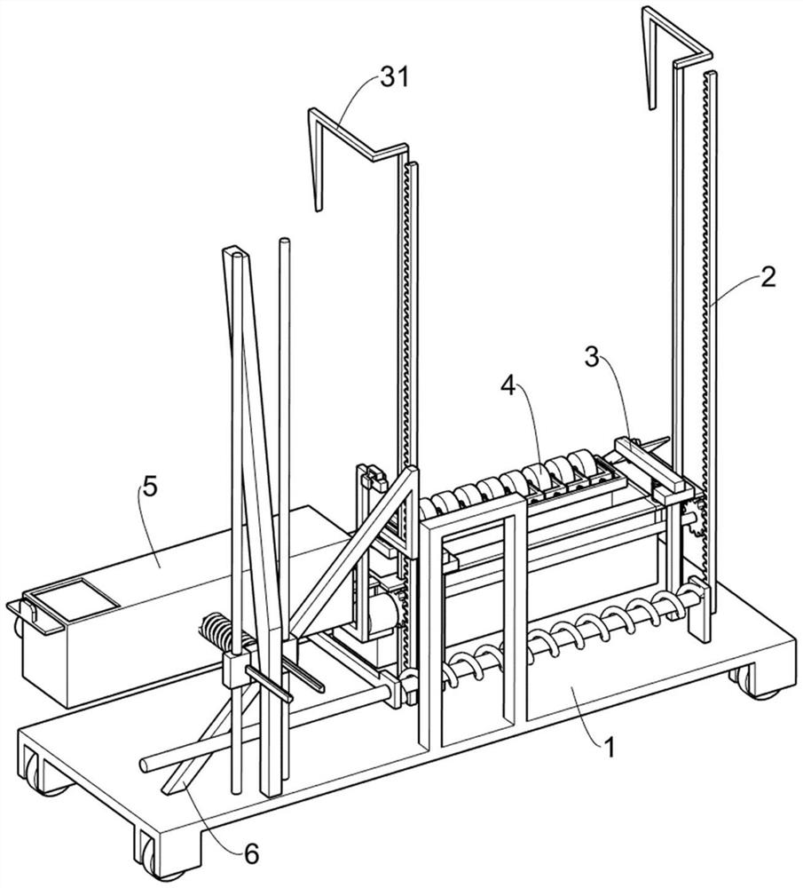
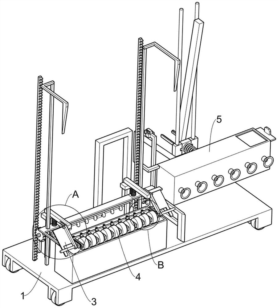
[0030] A shaving machine that can reserve the position of the wire box, such as Figure 1-11 Shown, include moving mechanism 1, lifting mechanism 2, turning mechanism 3 and napping mechanism 4, moving mechanism 1 is provided with lifting mechanism 2, and lifting mechanism 2 is provided with turning mechanism 3, and turning mechanism 3 is used for making nap tube 46 It can fully scrape to the top of the wall, and the lifting mechanism 2 is provided with a napping mechanism 4, which is used to reserve the position of the outlet box during the scraping process.

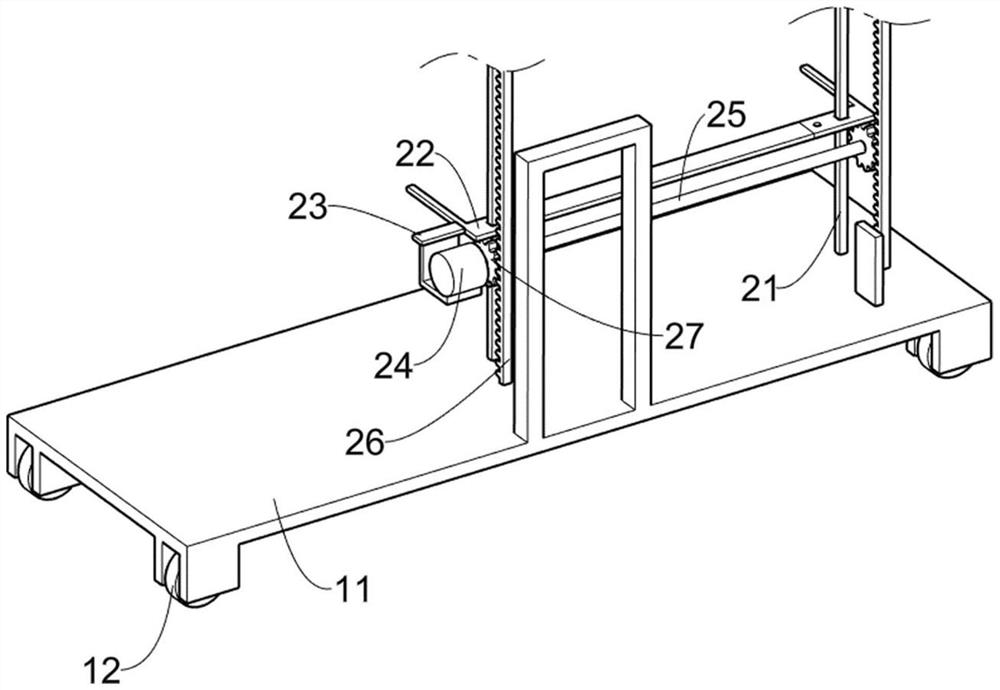
[0031] The moving mechanism 1 includes a hand push plate 11 and a rotating wheel 12. Two pairs of rotating wheels 12 are connected to the hand push plate 11 in a rotating manner. side of the wall.

[0032] The lifting mechanism 2 includes a first fixed rod 21, a first sliding frame 22, a first fixed frame 23, a motor 24, a rotating shaft 25, a rack 26 and a gear 27, and a pair of first fixed rods 21 are connected to the...

Embodiment 2

[0040] On the basis of Example 1, such as Figure 8-9 As shown, also includes a water spray mechanism 5, the water spray mechanism 5 is located on the moving mechanism 1, the water spray mechanism 5 is used to spray water to the wall in advance, the water spray mechanism 5 includes the third fixed rod 51, the second Wedge frame 52, fixed frame 53, first slider 54, second slider 55, squeeze plate 56, fourth return spring 57, sliding cover 58 and nozzle 59, a pair of third fixing rods connected to the top of push plate 11 51, the top of the push plate 11 is connected with a second wedge-shaped frame 52, the second wedge-shaped frame 52 is used to extrude the second slider 55 and the movement of the upper device, the first fixed frame 23 is connected with a fixed frame 53, and the third fixed The rod 51 is slidably connected with a first slider 54, and the two first sliders 54 are slidably connected with a second slider 55. The second slider 55 is in contact with the second wedge...

Embodiment 3

[0043] On the basis of Example 2, such as Figure 10-11 As shown, it also includes a burr shaving mechanism 6, which is arranged on the moving mechanism 1, and the burr shaving mechanism 6 is used to scrape off the burrs on the lower part of the wall. The burr shaving mechanism 6 includes a fourth fixed rod 61, a Four sliding frame 62, the 5th back-moving spring 63, scraper 64, the 4th fixed frame 65, rotating block 66, torsion spring 67 and wedge bar 68, are connected with the 4th fixed bar 61 on the push plate 11, the 4th fixed bar 61 The upper slide type is connected with a fourth sliding frame 62, and a fifth return spring 63 is connected between the fourth sliding frame 62 and the push plate 11, and the fifth return spring 63 is used to drive the fourth sliding frame 62 and its upper device to reset. The fourth sliding frame 62 is connected with a scraper 64, and the scraper 64 is used to scrape off the burrs on the lower part of the wall. The rotating block is connected...


PUM


Abstract

The invention relates to a dehairing machine, in particular to a dehairing machine capable of reserving the position of a wire box. The dehairing machine comprises a moving mechanism, a lifting mechanism, a rotating mechanism, a galling mechanism and the like; and the lifting mechanism is arranged on the moving mechanism, the rotating mechanism is arranged on the lifting mechanism, and the galling mechanism is arranged on the lifting mechanism. Through the cooperation of napping cylinders and the devices on the napping cylinders, one part of the napping cylinders in contact with the wire box can be extruded by the wire box in the dehairing process, one part of the napping cylinders and the devices on the napping cylinders can move towards a third fixing frame, so that the position of the wire box can be reserved in the dehairing process, therefore, the wire box can be protected, the dehaired wall surface is more attractive, and the effect that the dehairing position can be automatically reserved according to the position and the size of the wire box in the dehairing process is achieved.

Description

technical field [0001] The invention relates to a shaving machine, in particular to a shaving machine capable of reserving the position of a wire box. Background technique [0002] Wall scraping generally refers to an interface treatment on the base cement mortar before plastering or on the old wall. The method is to dip the cement mortar on the brush and scrape the wall through the brush. Treatment to make the surface of the wall rough, scraping can enhance the adhesion of the plastering layer or tile layer on the wall, which is convenient for subsequent painting of putty powder and other wall materials, and can reduce safety accidents caused by subsequent wall material falling off , so it is widely used in architectural decoration engineering. [0003] The existing technology is to spray water on the wall in advance, then dip the cement mortar with a brush, and then manually shave the wall with a brush, so that rough texture appears on the surface of the wall, but it cann...

Claims


Application Information

Patent Timeline
Patent Type & Authority Applications(China)
IPC IPC(8): E04F21/16
CPCE04F21/16
Inventor 刘久涛
Owner 山东林坔幕墙装饰有限公司
Why Eureka
Try Eureka