Pressure reduction type ball valve

A ball valve and valve body technology, which is applied in the field of pressure-reducing ball valves, can solve the problems of easy deformation and bending of the valve stem, affecting the service life of the ball valve stem, and unreduced water pressure, so as to improve the service life and avoid the impact of water flow on the valve plate. the effect of the activity

Pending Publication Date: 2021-11-26
KAISITONG VALVE
View PDF0 Cites 0 Cited by
  • Summary
  • Abstract
  • Description
  • Claims
  • Application Information

AI Technical Summary

Problems solved by technology

At present, the ball in the ball valve will be subjected to water pressure when the valve is closed, which will cause the valve stem to deform and bend easily, and after turning the valve stem to change the flow rate, the water pre

Method used


Image

  • Pressure reduction type ball valve
  • Pressure reduction type ball valve
  • Pressure reduction type ball valve

Examples


Embodiment Construction

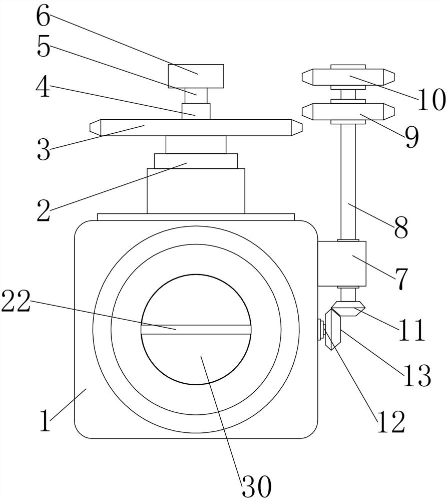
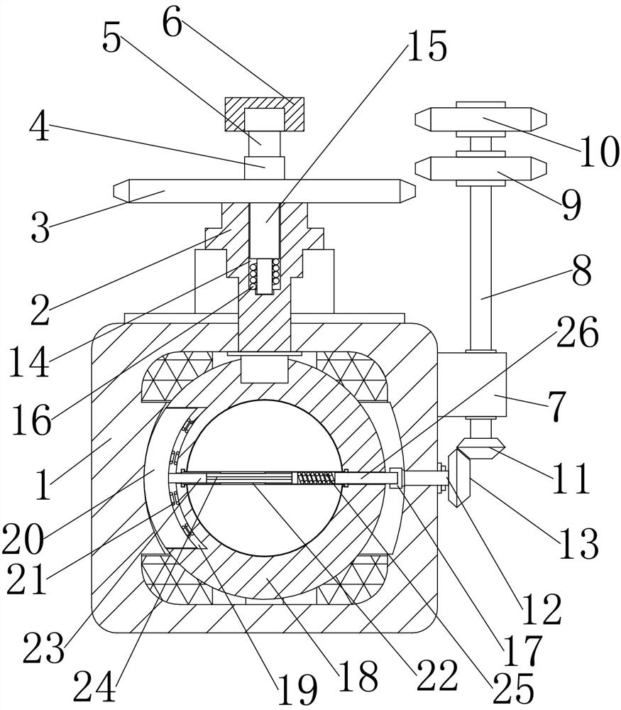
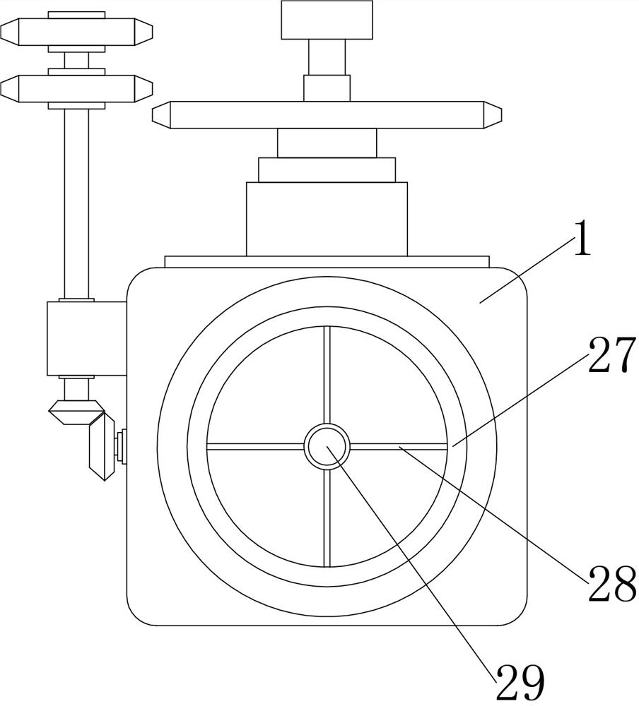
[0020] see Figure 1-Figure 5 , a decompression ball valve, including a valve body 1, a valve stem 2 and a ball 18, the ball 18 is rotatably connected inside the valve body 1, the valve stem 2 is fixed on the upper end of the ball 18, and the upper part of the valve stem 2 runs through The valve body 1 has a slot 14 on the upper end of the valve stem 2, and an insertion rod 15 is inserted inside the slot 14. The upper end of the insertion rod 15 extends out of the slot 14 and is fixed with a rotating gear 3. The bottom of the groove 14 is provided with a limit groove, the lower end of the insertion rod 15 is fixed with a rectangular limit rod, the limit rod is plugged into the limit groove, and the lower end of the insertion rod 15 is connected to the bottom of the slot 14. And be positioned at the back-moving spring 16 that is fixed on the outer side of the limit lever, when pressing down on the rotating gear 3, it can drive the insertion rod 15 to be inserted into the slot 1...


PUM


Abstract

The invention relates to the technical field of ball valves, in particular to a pressure reduction type ball valve. The pressure reduction type ball valve comprises a valve body, a valve rod and a ball, the ball is rotationally connected into the valve body, the valve rod is fixed to the upper end of the ball, the upper portion of the valve rod penetrates through the valve body, an inserting groove is formed in the upper end of the valve rod, an inserting rod is inserted into the inserting groove, the upper end of the inserting rod extends out of the inserting groove and is fixedly provided with a rotating gear, a rectangular lug is fixed to the upper end of the rotating gear, a support is fixed to the rear side of the upper end of the valve body, and a casing is fixed to the tail end of the support. When the valve needs to be opened, the rotating gear is pressed to the bottom and rotates, the rotating gear can drive the valve rod to rotate along with inserting connection of the limiting rod and the limiting groove, the valve rod can drive the ball to rotate at the moment, and therefore the ball valve can be opened and closed; when the ball valve is in the closed state, water pressure impacts a buffer block, the buffer block extrudes a buffer spring, meanwhile, a round rod, a cross rod and a rectangular rod synchronously move backwards, the rectangular rod extrudes a buffer ball, at the moment, the pressure of water pressure to the valve rod can be reduced, and therefore the service life can be prolonged.

Description

technical field [0001] The invention relates to the technical field of ball valves, in particular to a pressure-reducing ball valve. Background technique [0002] Ball valve is a valve whose opening and closing part (ball) is driven by the valve stem and rotates around the axis of the ball valve. It can be used for fluid regulation and control. At present, the ball in the ball valve will be subjected to water pressure when the valve is closed, which will cause the valve stem to deform and bend easily, and after turning the valve stem to change the flow rate, the water pressure on the ball in the ball valve will not decrease unless the ball valve is opened. Only when the hole and the water flow direction are on the same straight line can the pressure be reduced, which affects the service life of the ball valve stem. Contents of the invention [0003] The main purpose of the present invention is to provide a pressure-reducing ball valve to solve the problems raised in the a...

Claims


Application Information

Patent Timeline
IPC IPC(8): F16K5/06F16K5/10F16K31/53F16K31/60F16K47/02F16K1/22
CPCF16K5/0605F16K5/10F16K47/023F16K31/535F16K31/60F16K1/224
Inventor 李军辉金定存腾新庭腾楠林虎腾慧琼杨跃苗
Owner KAISITONG VALVE
Why Eureka
Try Eureka