
Laser spot positioning method applied to security and protection monitoring, distance measuring method, medium and equipment

A laser spot and security monitoring technology, which is applied in the fields of laser spot positioning method, medium and equipment, and distance measurement method, can solve the problems of low degree of automation, unguaranteed accuracy, and inability to accurately obtain laser spot position information, so as to improve the degree of automation , Improve the effect of positioning accuracy

Pending Publication Date: 2021-11-26
GOSUNCN TECH GRP
View PDF0 Cites 0 Cited by
  • Summary
  • Abstract
  • Description
  • Claims
  • Application Information

AI Technical Summary

Problems solved by technology

[0003] The embodiment of the present invention provides a laser spot positioning method, ranging method, medium and equipment applied to security monitoring to solve the problem of inability to accurately obtain the position information of the laser spot in the video screen and the degree of automation in the existing video security monitoring Low, low monitoring efficiency, and accuracy cannot be guaranteed

Method used


Image

  • Laser spot positioning method applied to security and protection monitoring, distance measuring method, medium and equipment
  • Laser spot positioning method applied to security and protection monitoring, distance measuring method, medium and equipment
  • Laser spot positioning method applied to security and protection monitoring, distance measuring method, medium and equipment

Examples


Embodiment Construction

[0047] The following will clearly and completely describe the technical solutions in the embodiments of the present invention with reference to the accompanying drawings in the embodiments of the present invention. Obviously, the described embodiments are some of the embodiments of the present invention, but not all of them. Based on the embodiments of the present invention, all other embodiments obtained by persons of ordinary skill in the art without creative efforts fall within the protection scope of the present invention.

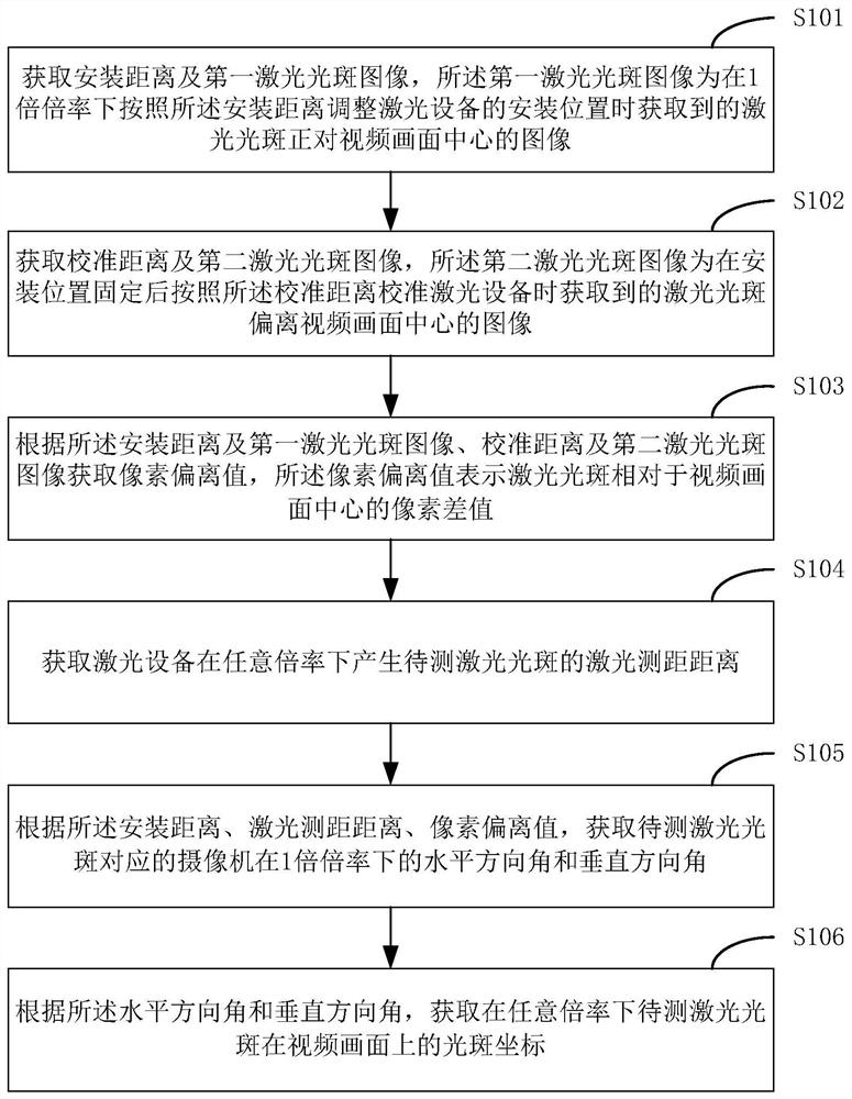
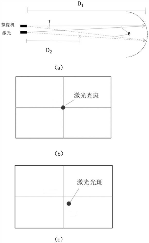
[0048] This embodiment provides a laser spot positioning method applied to security monitoring. By adjusting the installation distance D1 so that the laser spot falls on the center of the video screen, the physical position of the laser device is determined and fixed, and the first laser spot image is obtained. ; Make the laser spot deviate from the center of the video picture by calibrating the laser device, and obtain the calibration distance D2 and t...


PUM


Abstract

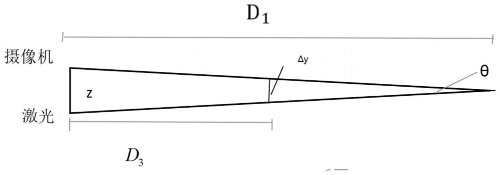
The invention discloses a laser spot positioning method applied to security monitoring, and the method comprises the steps: enabling a laser spot to fall at the center of a video image through adjusting a mounting distance, determining the physical position of laser equipment, fixing the physical position, and obtaining a first laser spot image; enabling the laser spot to deviate from the center of the video picture through calibration laser equipment, and obtaining a calibration distance and a second laser spot image; determining a pixel deviation value according to the first laser spot image and the second laser spot image; determining a horizontal pixel compensation coefficient kx and a vertical direction compensation coefficient of a to-be-measured laser spot through the mounting distance and the laser ranging distance D3, and further obtaining spot coordinates of the to-be-measured laser spot on the video picture under the condition of one magnification; converting the spot coordinate into a horizontal direction angle and a vertical direction angle of a camera corresponding to the to-be-measured laser spot at one magnification; and according to the horizontal direction angle and the vertical direction angle, acquiring a light spot coordinate of the to-be-measured laser spot on the video picture under any multiplying power. According to the invention, the position information of the laser spot in the video picture can be accurately obtained on the basis of existing video security and protection monitoring, the positioning precision of the laser spot is improved, and the automation degree of laser spot positioning is improved.

Description

technical field [0001] The invention relates to the field of video security monitoring, in particular to a laser spot positioning method, distance measuring method, medium and equipment applied to security monitoring. Background technique [0002] With the development of the security industry, the technology of monitoring equipment is becoming more and more mature, and the technical requirements of users for monitoring equipment are also increasing. However, the existing security monitoring products do not have integrated laser ranging function, and cannot accurately obtain the position information of the laser spot in the video screen, and the positioning accuracy of the laser spot is low. If you need to measure the distance from the monitoring equipment to the monitored object, you need to use external tools and manually measure at the installation site of the monitoring equipment. The degree of automation is low, resulting in low work efficiency and the accuracy of measur...

Claims


Application Information

Patent Timeline
Patent Type & Authority Applications(China)
IPC IPC(8): G01C3/02G01C11/02G01C11/30
CPCG01C3/02G01C11/02G01C11/30
Inventor 杨伟亮陈志强陈利军
Owner GOSUNCN TECH GRP
Learn More