Apparatus and methods for particle testing

A technology of testing device and testing method, which is applied in the direction of measuring device, particle and sedimentation analysis, particle size analysis, etc., can solve the problem that it is not allowed to study the particles in the gas environment, and achieve the effect of a wide range of applications

Pending Publication Date: 2021-11-26
MAX PLANCK GESELLSCHAFT ZUR FOERDERUNG DER WISSENSCHAFTEN EV
View PDF12 Cites 0 Cited by
  • Summary
  • Abstract
  • Description
  • Claims
  • Application Information

AI Technical Summary

Problems solved by technology

However, these systems do not allow the study of particles in gaseous environments, in particular to determine their number or size

Method used


Image

  • Apparatus and methods for particle testing
  • Apparatus and methods for particle testing
  • Apparatus and methods for particle testing

Examples


Embodiment Construction

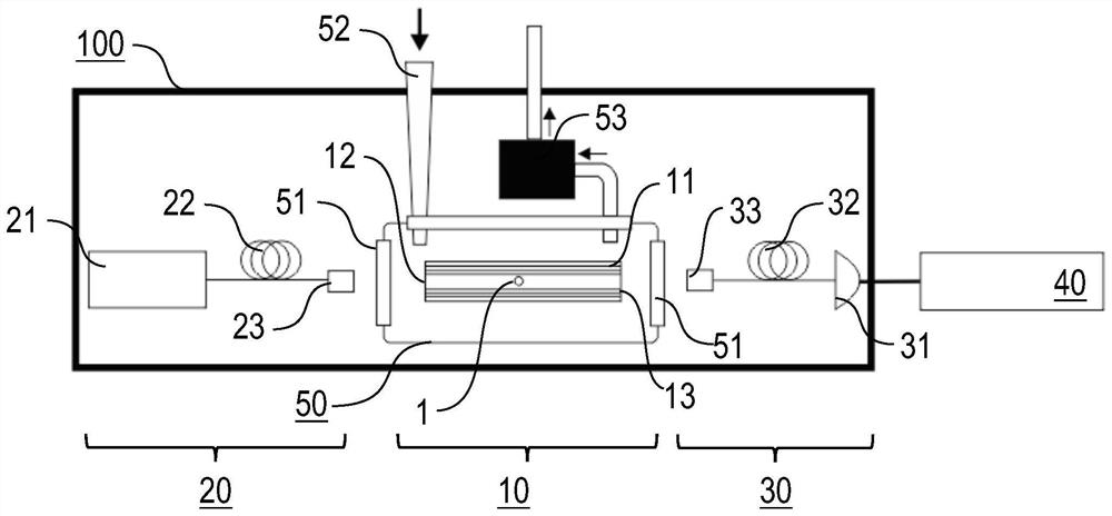
[0053] Embodiments of the invention are described below with particular reference to particle testing using HC-PCF. The invention is not limited to this embodiment but can be implemented using other hollow waveguide types such as capillary, ARROW waveguides. The details of collecting and optionally further preparing the samples to be tested are not described, since sample collection and preparation techniques are known per se from conventional analytical techniques. For example, a sample may be collected by aspirating or collecting air or other reactive gas or a portion of the sample liquid from the environment or an enclosed space. The invention is suitable for testing samples under gaseous or liquid conditions. In particular, liquid samples can be tested directly by directing the liquid sample through an optical waveguide, or by converting the liquid sample to a gaseous state, for example using a medical nebulizer, while retaining particles that may be present in the sample...


PUM

PropertyMeasurementUnit
diameteraaaaaaaaaa

Abstract

A particle testing apparatus (100), being configured for investigating particles in a fluid medium, comprises a waveguide device (10) including a hollow optical waveguide (11) having an input end (12) and an output end (13), an irradiation device (20) including a laser source (21) being arranged for optically trapping at least one particle at the input end (12) of the optical waveguide (11) and propelling the particle through the optical waveguide (11) toward the output end (13) thereof, and a measuring device (30) being arranged for sensing the at least one particle in the optical waveguide (11), wherein the measuring device (30) is arranged for measuring an optical transmission of the optical waveguide (11). Furthermore, a particle testing apparatus is described.

Description

technical field [0001] The present invention relates to a particle testing apparatus for the study of particles in fluid media (eg, gaseous or liquid environments), particularly employing the detection of particles propelled in hollow gas or liquid filled optical waveguides. Furthermore, the invention relates to a particle testing method for studying particles in a fluid medium. The application of the invention is suitable, for example, in the field of environmental or materials research or in monitoring chemical or physical processes. Background technique [0002] In this specification, reference is made to the following prior art, which illustrates the technical background of the present invention, and related art: [0003] [1] R.S.Gao et al., "Aerosol Science and Technology" 47, 137-145 (2013); [0004] [2] Met One Instruments Inc.: [0005] https: / / metone.com / indoor-controlled-environments / controlled-environments / model-804-handheld-particle-counter / ; [0006] [3] X.-...

Claims


Application Information

Patent Timeline
Patent Type & Authority Applications(China)
IPC IPC(8): G01N15/02G01N15/14G01N15/00
CPCG01N2015/0046G01N2015/0038G01N15/1459G01N2015/1493G01N1/2273G01N15/0211G01N15/1434
Inventor 菲利普·罗素理查德·泽尔特纳谢尚然阿比纳夫·夏尔马
Owner MAX PLANCK GESELLSCHAFT ZUR FOERDERUNG DER WISSENSCHAFTEN EV
Why Eureka
Try Eureka