Vehicular device, and control method for vehicular device
A control method, technology for vehicles, applied in the direction of vehicle components, transportation and packaging, electrical circuits or fluid lines, etc., to solve problems such as cache memory, increased bus load, etc.
- Summary
- Abstract
- Description
- Claims
- Application Information
AI Technical Summary
Problems solved by technology
Method used
Image

Examples
no. 1 approach
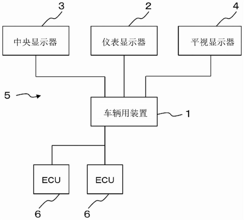
[0044] Hereinafter, the first embodiment will be described. Such as figure 1 As shown, the vehicle device 1 constitutes, for example, a cockpit system 5 including three displays of an instrument display 2 , a center display 3 , and a head-up display 4 .
[0045] It is assumed that the meter display 2 is composed of, for example, a liquid crystal display or an organic EL display, and is installed near the front of the driver on the dashboard. It is assumed that the center display 3 is composed of, for example, a liquid crystal display or an organic EL display, and is installed near the center console.
[0046] It is assumed that the head-up display 4 is composed of, for example, a liquid crystal display or an organic EL display, or a projector that projects an image onto a front window, and is installed on the dashboard near the front of the driver. However, the number, arrangement, or configuration of the displays are examples and are not limited thereto.
[0047] Furthermo...
no. 2 approach
[0093] Next, a second embodiment will be described. In the second embodiment, a configuration example of the vehicle device 1 that is different from the first embodiment will be described. In addition, for the sake of simplification of description, the vehicle device 1 , the OS 20 , or the application 21 will be described with the same reference numerals. In addition, the method of synchronous control etc. is the same as that of 1st Embodiment.
[0094]
[0095] In the first configuration example, such as Figure 12 As shown, the vehicle device 1 executes the hypervisor 40 on the CPU 10 , and executes a plurality of, for example, two OS 20A and OS 20B on the hypervisor 40 . At this time, OS20A is allocated to CPU module 16A, and OS20B is allocated to CPU module 16B. In this embodiment, it is assumed that OS 20A is in charge of relatively high real-time processing, and OS 20B is in charge of relatively low real-time processing.
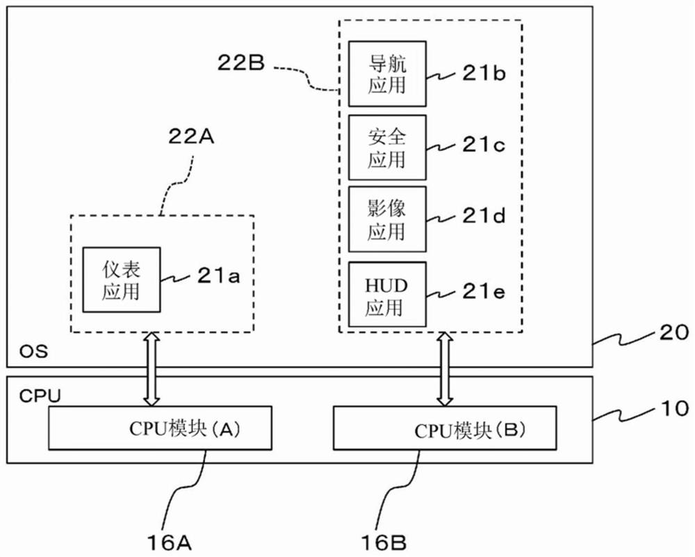
[0096] Therefore, in OS 20A, for example, ...
no. 3 approach
[0104] Next, a third embodiment will be described. In the third embodiment, an example in which the surface is synchronized between the vehicle device 1 and the ECU 6 will be described. In addition, in order to simplify description, the vehicle apparatus 1, OS20, or the application 21 is demonstrated using the same code|symbol. In addition, an embodiment in which the configuration of the vehicle device 1 is the same as that of the first embodiment and the second embodiment, and the method of synchronous control is the same as that of the first embodiment can be employed.
[0105] In the third embodiment, if Figure 14 As shown, the vehicle device 1 is connected to another ECU 6 in a communicable manner, and uses the same control method as the first embodiment to make the surface drawn on the physical surface 30 by the synchronization unit on its own side and the surface on the ECU 6 side. The surfaces delineated by the other physical planes 30 are synchronized.
[0106] Spe...
PUM
 Abstract
Description
Claims
Application Information
 - R&D
- Intellectual Property
- Life Sciences
- Materials
- Tech Scout
- Unparalleled Data Quality
- Higher Quality Content
- 60% Fewer Hallucinations
Browse by: Latest US Patents, China's latest patents, Technical Efficacy Thesaurus, Application Domain, Technology Topic, Popular Technical Reports.
© 2025 PatSnap. All rights reserved.Legal|Privacy policy|Modern Slavery Act Transparency Statement|Sitemap|About US| Contact US: help@patsnap.com