Hanging device, brake clamp unit adopting same and hanging connection method

A hanging device and brake caliper technology, applied in the field of rail transit, can solve the problems of inability to relieve fatigue, poor anti-fatigue performance of four-point hoisting, etc., and achieve the effects of overall weight reduction, good manufacturability, and reduction of internal stress.

Pending Publication Date: 2021-11-30
CRRC QISHUYAN INSTITUTE CO LTD +1
View PDF4 Cites 0 Cited by
  • Summary
  • Abstract
  • Description
  • Claims
  • Application Information

AI Technical Summary

Problems solved by technology

This technical solution further reduces the installation space by separating the left and right mounting bases of the hoisting components. However, since the two mounting bases need to be rigidly assembled and connected by the front and rear suspension shafts, a rigid structure is formed between the front and rear suspensions on the same side, which cannot relieve the vehicle from running. Fatigue caused by bumps and vibrations in the front and rear directions, so this technical solution fails to properly solve the problem of poor fatigue resistance of four-point hoisting

Method used


Image

  • Hanging device, brake clamp unit adopting same and hanging connection method
  • Hanging device, brake clamp unit adopting same and hanging connection method
  • Hanging device, brake clamp unit adopting same and hanging connection method

Examples


Embodiment 1

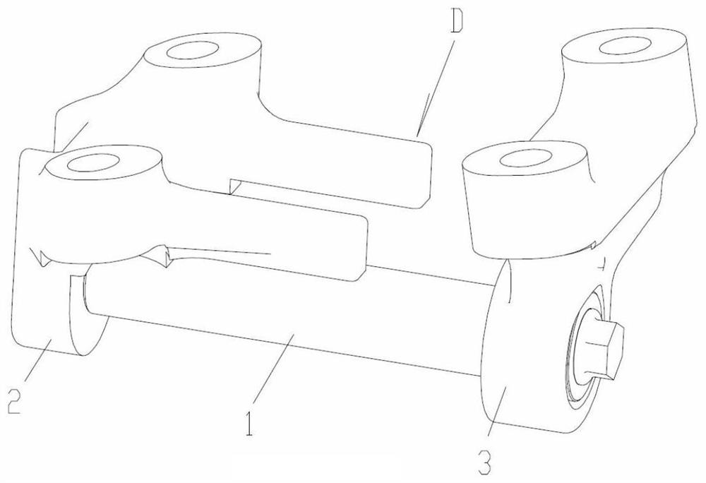
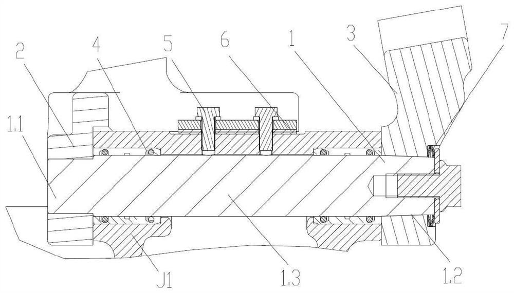
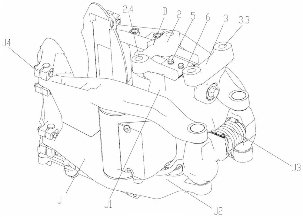
[0037] The hanging device D of this embodiment is as figure 1 with figure 2 As shown, it includes a front hanger 2 and a rear hanger 3 which are separated from each other, and a hanger pin 1 for connecting the main body J of the clamp during installation.

[0038] Front suspension 2 such as Figure 4 to Figure 7 As shown, there is a front main body 2.1 that is vertically T-shaped, and the bottom of the front main body 2.1 is shaped on a horizontal front piercing hole 2.2. The front end surface of the upper part of the front main body 2.1 is in the shape of a curved arc protruding forward, and the two ends are respectively formed with vertical front hanging holes 2.4. The rear parts of the two front hanging holes 2.4 respectively extend out the positioning rods 2.3 whose lower surfaces are formed with anti-yaw constraint planes 2.31. As shown in FIG. 2 and FIG. 3 , the anti-yaw constraint plane 2.31 is used to cooperate with the pressure plate 6 fixed on the top of the mai...


PUM


Abstract

The invention relates to a hanging device of a brake clamp unit, and belongs to the technical field of rail transit. The device consists of a front hanger, a rear hanger and a hanger pin shaft, wherein the front hanger and the rear hanger are separated from each other; the front hanger is provided with a front main body which is T-shaped in the vertical direction; the lower part of the front main body is provided with a front penetrating hole, and two ends of the upper part are respectively provided with a front hanging hole; a positioning rod provided with an anti-deflection constraint plane extends out of the rear part of the front penetrating hole; the rear hanger is provided with a T-shaped rear main body; a rear penetrating hole is formed in the lower part of the rear main body, and vertical rear hanging holes are respectively formed in two ends of the upper part of the rear main body; the two ends of the hanger pin shaft are connected with the front penetrating hole and the rear penetrating hole respectively; and at least one end of the hanger pin shaft is in elastic wedging connection with one of the front penetrating hole and the rear penetrating hole, and the outer diameter between the two ends of the hanger pin shaft is matched with the inner diameter of the mounting hole of a clamp body. The hanging device is good in manufacturability, and more importantly, internal stress can be effectively reduced, so that the fatigue life of the hanging device of a brake clamp unit is obviously prolonged, and the overall weight is obviously reduced.

Description

technical field [0001] The invention relates to a suspension device for a brake caliper unit, in particular to a split suspension connection assembly suitable for a brake caliper unit of an urban rail vehicle, and also relates to a brake caliper unit using the device and A hanging connection method belongs to the technical field of rail transit. Background technique [0002] The brake caliper unit is an important part to ensure the safety of rail vehicles. There are three-point hoisting and four-point hoisting methods for its installation (see the 2015 China Railway Society Vehicle Committee Fast Truck Braking Technology Exchange Conference Proceedings "Brake Caliper Application Research of Units and Brakes on Express Freight Cars), the former requires a larger bogie, so the installation space is larger; the latter has a compact structure and is suitable for occasions where the brake installation space is small. [0003] Due to the limited installation space, the applicant ...

Claims


Application Information

Patent Timeline
Patent Type & Authority Applications(China)
IPC IPC(8): B61H5/00B61H13/20
CPCB61H5/00B61H13/20
Inventor 兴百宪韩红文郑志立苟青炳
Owner CRRC QISHUYAN INSTITUTE CO LTD
Why Eureka
Try Eureka