
Interactive lifting formwork device and construction method

A technology of lifting rods and lifting units, which is applied in the field of interactive lifting formwork devices, can solve the problems of high labor intensity, poor quality perception, and large investment in turnover materials, so as to reduce labor intensity, excellent quality perception, and high modularization degree Effect

Active Publication Date: 2021-06-18
河南省第二建设集团有限公司
View PDF9 Cites 0 Cited by
  • Summary
  • Abstract
  • Description
  • Claims
  • Application Information

AI Technical Summary

Problems solved by technology

[0006] In view of the above situation, in order to overcome the defects of the prior art, the present invention provides an interactive lifting formwork device and construction method to solve the problems of high labor intensity, large investment in turnover materials and poor quality perception in the construction of the wall of the silo structure. good question

Method used


Image

  • Interactive lifting formwork device and construction method
  • Interactive lifting formwork device and construction method
  • Interactive lifting formwork device and construction method

Examples


Embodiment 1

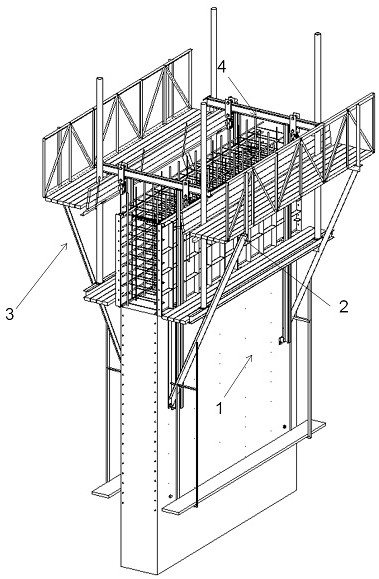
[0046] Embodiment one: by Figure 1 to Figure 11 Given, an interactive lifting formwork device, including an attachment unit 1, a formwork unit 2, a triangular truss operating platform unit 3 and a lifting unit 4, such as figure 1 shown;

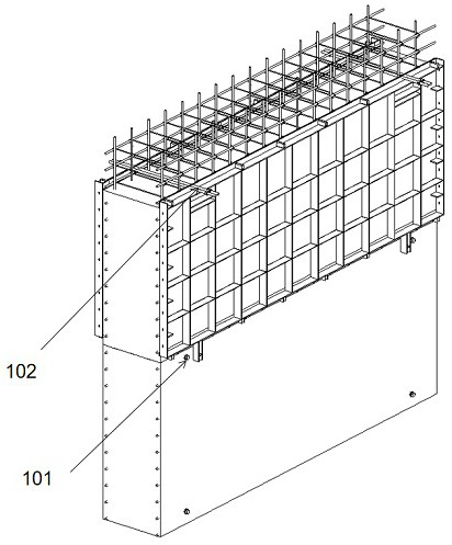
[0047] The attachment unit 1 includes a climbing cone 101 and a pair of drawing rods 102, such as figure 2 shown;

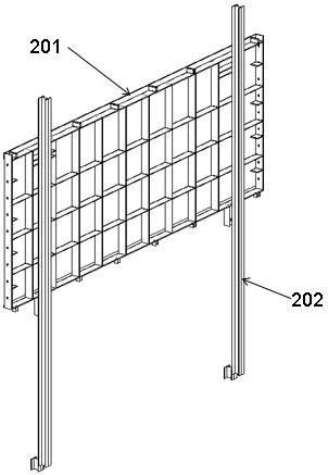
[0048] The template unit 2 includes a template 201 and a platform lifting rod 202, and the platform lifting rod 202 is attached to the template 201, such as image 3 shown;

[0049] The triangular truss operating platform unit 3 (see Figure 4 and Figure 5 ) includes a lower operating platform, a middle operating platform and an upper operating platform, the lower operating platform includes a hanger 301 and a lower aisle plate 302, the middle operating platform includes a middle tripod structure 303 and a middle aisle plate 304, the upper operating platform The platform includes an upper tripod structure 305, an upper ...

Embodiment 2

[0056] Embodiment 2: An interactive lifting construction method:

[0057] S1: Carry out the construction of the first plate tube wall (see Figure 8 ): first set up the inner and outer fastener type steel pipe scaffolding as the operating frame (5), bind the first steel frame (6) and pre-bury the climbing cone 101 in the first steel frame (6), and then hang the formwork (201) and the filling formwork (9) at the bottom, set the leveling steel pipe (7) through the operation frame (5), and support and level the formwork 201 through the leveling steel pipe (7), and further use the climbing cone bracket (8), to The drawing rod (102) fixes the template 201 and the supplementary template (9), and then pours the first slab of concrete;

[0058] S2: After the first slab of concrete reaches the design strength, remove the formwork (201), bind the steel skeleton of the second slab, remove the operating frame (5), and install and fix the triangular truss inside and outside the first slab...


PUM


Abstract

The invention relates to the technical field of industrial building structure construction, in particular to an interactive lifting formwork device and a construction method, and solves the defects of high labor intensity, large turnover material investment, poor quality and appearance and the like of a traditional process for silo structure cylinder wall construction. The interactive lifting formwork device comprises an attachment unit, a template unit, a triangular truss operation platform unit and a lifting unit; the attachment unit comprises a climbing cone and an opposite-pulling lead screw; the template unit comprises a template and a platform lifting rod; the triangular truss operation platform unit comprises a lower operation platform, a middle operation platform and an upper operation platform; and cylinder wall construction is implemented by interactively lifting the template unit and the triangular truss operation platform unit. The construction method is free of hydraulic pressure, is suitable for relatively large-diameter silo construction, and has a good development prospect in the technical field of industrial building structure construction.

Description

technical field [0001] The invention relates to the technical field of industrial building structure construction, in particular to an interactive lifting formwork device and a construction method. Background technique [0002] In industrial buildings such as thermal power plants, large-diameter circular cross-section structures such as coal storage silos generally adopt reinforced concrete silo structures, and the construction techniques usually used in the construction of the silo walls include: Plate process and all-steel large formwork turning process. [0003] The three commonly used construction techniques mentioned above all have corresponding deficiencies; the hydraulic slipform technique is usually suitable for silo structures with small diameters. Not only is the maintenance of the hydraulic control system difficult, the risk of oil leakage is high, and the formwork system is prone to torsion and concrete surface tension. Cracks, tube wall slurry (oil) pollution a...

Claims


Application Information

Patent Timeline
IPC IPC(8): E04G11/20E04G21/00E04G21/16
CPCE04G11/20E04G21/00E04G21/16
Inventor 苏群山张俊峰高志强汤应武杜存军王涛张记山桑润溪王庆伟陈建中闫龙广董新红郭小军都宏全范艳超张兰阁曹天祥曹剑刘攀张书刚李自亮侯振超李旭升陈施渝周景路邢会远
Owner 河南省第二建设集团有限公司
Learn More