Glass lining equipment

A glass-lined and equipment technology, applied in the field of glass equipment, can solve problems such as damage to equipment connections, inability to open safety valves, and impact at equipment connections.

Inactive Publication Date: 2021-11-30
操琴琴
View PDF0 Cites 0 Cited by
  • Summary
  • Abstract
  • Description
  • Claims
  • Application Information

AI Technical Summary

Problems solved by technology

[0003] Aiming at the deficiencies of the prior art, the present invention provides a glass-lined equipment, which solves the problem that the generation of high pressure will inevitably lead to the impact of pressure on the weak position at the connection of the equipment, and when the internal pressure is too high, it is necessary to manually check for safety. The valve is opened to adjust the internal pressure of the equipment, but in the production process, there are bound to be various situations that will attract human attention, resulting in the situation that the internal pressure of the equipment is too high, and the safety valve cannot be opened, resulting in internal failure of the equipment. The problem of damage to the connection caused by excessive pressure

Method used


Image

  • Glass lining equipment
  • Glass lining equipment
  • Glass lining equipment

Examples


Embodiment 1

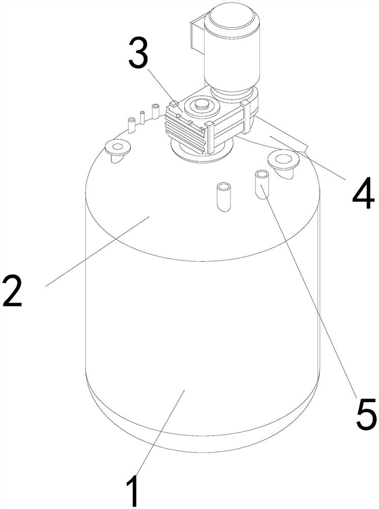
[0025] as attached figure 1 to attach Figure 5 As shown, the present invention provides a glass-lined equipment, the structure of which includes a cylinder body 1, a top cover 2, a safety valve 3, a filling hole 4, and a pressurizing tube 5, and the outer wall of the lower end of the top cover 2 is snapped The outer wall of the lower end of the safety valve 3 is nested and fixed on the inner wall of the center of the top cover 2, the lower end of the injection hole 4 is welded and fixed on the upper end of the top cover 2, and the lower end of the pressure tube 5 is embedded and fixed. fixed on the upper surface of the top cover 2;

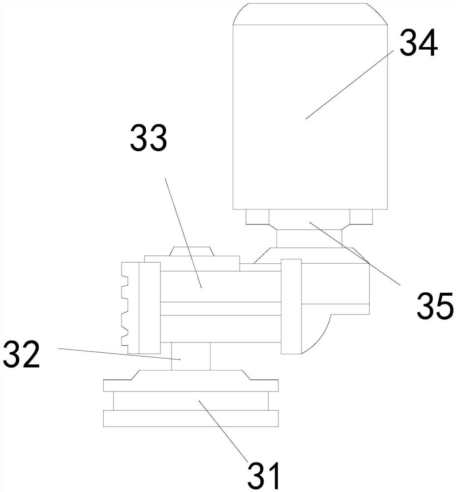
[0026] The safety valve 3 is composed of a fixed seat 31, an exhaust rod 32, a main body 33, a driver 34, and an assembly seat 35. The sleeve is assembled on the inner wall of the main body 33, the upper end on the right side of the main body 33 is welded and fixed to the lower end of the assembly seat 35, the lower end of the driver 34 is fixe...

Embodiment 2

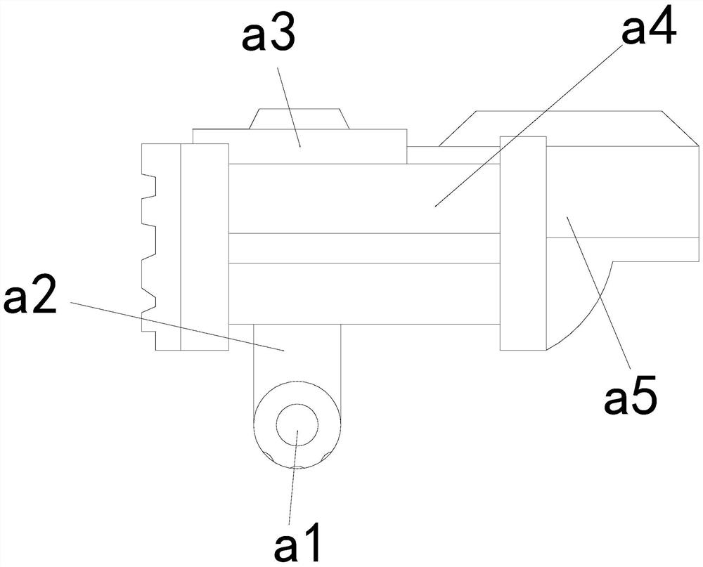
[0032] as attached Figure 4As shown: the rectification mechanism a1 is composed of an air inlet b1, a ring body b2, a push block b3, a rectification ring b4, and a blade b5. The outer wall of the middle section of the block b3 is gap-fitted with the inner wall of the upper end of the ring body b2, the outer wall of the rectifying ring b4 is nested and fitted on the inner wall of the ring body b2, the lower end of the blade b5 is welded and fixed to the outer wall of the rectifying ring b4, and the upper end of the push block b3 is connected to the movable seat There is a movable fit at the lower end of d1, and there are five blades b5 in total. The structure is an inclined structure, arranged circularly on the outer wall of the rectifying ring b4, guided by the angle of the structure, so that the high-pressure airflow entering the ring b2 can drive the blades b5 to rotate.

[0033] as attached Image 6 to attach Figure 7 As shown: the pressure relief valve a3 is composed ...


PUM


Abstract

The invention provides glass lining equipment. The glass lining equipment structurally comprises a cylinder body, a top cover, a safety valve, a material injection hole and a pressurizing pipe, the outer wall of the lower end of the top cover is clamped to the inner wall of the upper end of the cylinder body through a buckle, the outer wall of the lower end of the safety valve is embedded and fixed to the inner wall of the center of the top cover, the lower end of the material injection hole is welded and fixed to the upper end of the top cover, and the lower end of the pressurizing pipe is embedded and fixed to the surface of the upper end of the top cover. When glass is processed and the pressure in the cylinder body is too high, high-pressure air can enter a ring body through air inlet holes, the too high pressure can blow blades to enable a rectifying ring to rotate, an extension plate is opened through centrifugal force generated by rotation, a push block is pushed to rise through the extension plate, so that high-pressure air can be discharged into the pressure release valve through an empty groove formed in the periphery of the push block, the high-pressure air is discharged, and the situation that the equipment is damaged due to the fact that the internal pressure of the equipment is too high under the condition of manual distraction is avoided.

Description

technical field [0001] The invention relates to the field of glass equipment, and more specifically relates to a glass-lined equipment. Background technique [0002] Glass-lined equipment is a kind of glass processing equipment used in glass production. By lining the inner surface of the equipment with high-silica-containing glass, it is firmly adhered to the metal surface after high-temperature burning to form a composite material product. When processing glass, the inside of the equipment needs to be heated and pressurized, the glass is melted by heat, the plasticity of the glass is improved, and the glass is extruded to the inner surface of the equipment by high-pressure air, but the generation of high pressure is bound to It will cause the weak position of the equipment connection to be impacted by pressure, and when the internal pressure is too high, it is necessary to manually open the safety valve to adjust the internal pressure of the equipment, but in the production...

Claims


Application Information

Patent Timeline
Patent Type & Authority Applications(China)
IPC IPC(8): C23D5/00
Inventor 操琴琴
Owner 操琴琴
Why Eureka
Try Eureka