Gas detector for environment detection

A gas detector and environmental detection technology, which is applied to the structural details of gas analyzers, analysis of gas mixtures, instruments, etc., can solve problems such as inability to remove debris, damage to the detector, and damage to the detector

Pending Publication Date: 2021-11-30
刘东
View PDF1 Cites 0 Cited by
  • Summary
  • Abstract
  • Description
  • Claims
  • Application Information

AI Technical Summary

Problems solved by technology

[0004] Although the above-mentioned combined gas analysis data analysis device adopts a movable design, the bottom of the device body is provided with a self-locking universal wheel, which is beneficial to the movement of the device body, and it is a combinable design, and the gas detector is fixed by the clamping device. , the gas detector is easy to maintain and replace, the clamping device is set on the lifting and rotating mechanism, the gas detector can be flexibly called, and the setting is provided by an independent rechargeable power supply, which can provide power for the device body to move and work independently, and the actual application value of the overall device High, but there are still the following disadvantages: when used in outdoor environments such as parks, the air inlet and outlet holes of the solid detector in the existing gas detector are all set on the outer surface of the solid detector, which is easy to be damaged in rainy weather Ingress of water droplets and moisture will cause damage to the detection device and seriously damage the detector, and it is impossible to remove the debris accumulated at the connection between the peripheral hole of the external detector and the outside world, which will easily cause debris to enter the interior and cause damage to the detector

Method used


Image

  • Gas detector for environment detection
  • Gas detector for environment detection
  • Gas detector for environment detection

Examples


Embodiment approach

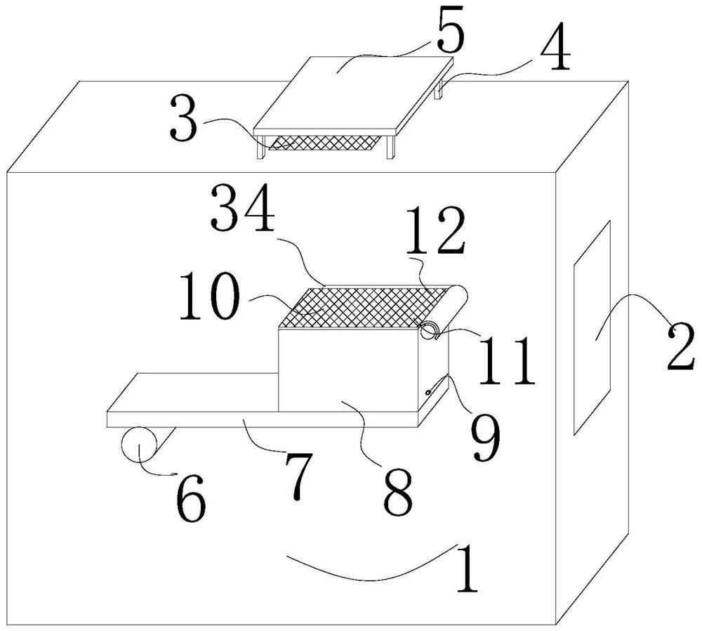
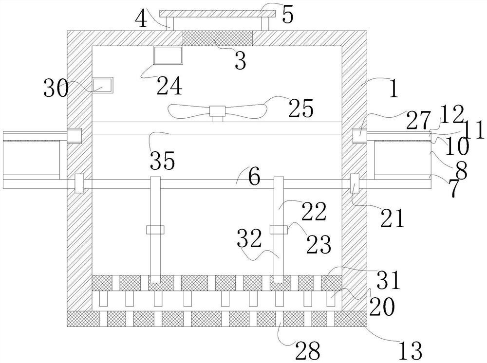
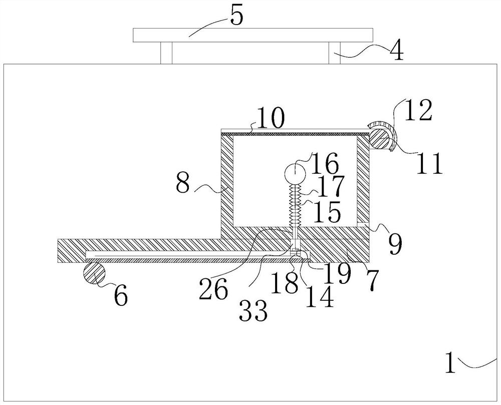
[0035] As an embodiment of the present invention, brushes 11 are rotatably connected to the outer surfaces of the front and rear ends of the housing 1 at the upper right of the fourth filter 10;

[0036] When working, the water tank 8 and the fixed plate 7 rotate clockwise, and the water tank 8 drives the fourth filter screen 10 fixedly connected to the upper end to rotate clockwise, and the outer surface of the brush 11 is attached to the outer surface of the upper end of the fourth filter screen 10, and the fourth filter screen 10 rotates clockwise to drive the brush 11 slidingly connected to the upper right to rotate counterclockwise and move relatively horizontally, the upper surface of the fourth filter screen 10 and the outer surface of the brush 11 are always attached, and the relative position remains unchanged, so that the brush 11 Clean up the sundries on the outer surface of the upper end of the fourth filter screen 10 to prevent the sundries from covering the fourth...


PUM


Abstract

The invention relates to the technical field of gas detection, in particular to a gas detector for environment detection, which comprises a shell. A display is fixedly connected to the middle of the left side of the shell, a third filter screen is fixedly connected to the middle of the upper end of the shell, and connecting rods are fixedly connected to the outer surface of the upper end of the shell and located on two sides of the third filter screen. The upper end of the connecting rod is fixedly connected with a shielding plate, the upper end of the interior of the shell is fixedly connected with a fixing rod, the fixing rod is movably connected with an exhaust fan, and the position, corresponding to the third filter screen, of the inner wall of the upper end of the shell is movably connected with a detection component. When use in a park and other outdoor environment, a water tank is fixedly connected with a first rotating shaft through a fixing plate, so that the water tank rotates to drive the first rotating shaft to rotate in rainy days and full of moisture, the first rotating shaft rotates to drive a second filter screen to move downwards, a fixing column below the second filter screen is exactly embedded into a through hole, and closed protection of the detector is achieved.

Description

technical field [0001] The invention relates to the technical field of gas detection, in particular to a gas detector for environmental detection. Background technique [0002] A gas detector, also known as a gas detector, is an instrumentation tool used to detect the composition and content of a gas. It mainly uses a gas sensor to detect the type of gas present in the environment or to detect the concentration of gas in the environment emitted by the gas. Gas sensors mainly refer to portable, fixed, and hand-held gas detectors, among which the portable ones are easy to carry and flexible to use; the fixed ones can alarm and monitor in real time; the portable ones have high measurement accuracy and are widely used. [0003] Existing patent (notification number: CN211652763U) a combined gas analysis data analysis device, including a bottom plate, self-locking universal wheels are arranged at the four corners of the bottom of the bottom plate, and the middle position of one si...

Claims


Application Information

Patent Timeline
IPC IPC(8): G01N33/00G01N1/22B01D46/12B01D29/64B01D29/03
CPCG01N33/0009G01N1/2205B01D46/12B01D29/03B01D29/643
Inventor 刘东庞敏
Owner 刘东
Why Eureka
Try Eureka