Resonant grounding power distribution network high-resistance grounding fault line selection method and system and storage medium
A high-resistance grounding fault, resonant grounding technology, applied in the fault location, detecting faults by conductor type, short-circuit testing, etc., can solve the problems of high-resistance grounding fault detection and line selection, etc. long-running effects
- Summary
- Abstract
- Description
- Claims
- Application Information
AI Technical Summary
Problems solved by technology
Method used
Image
Examples
Embodiment 1
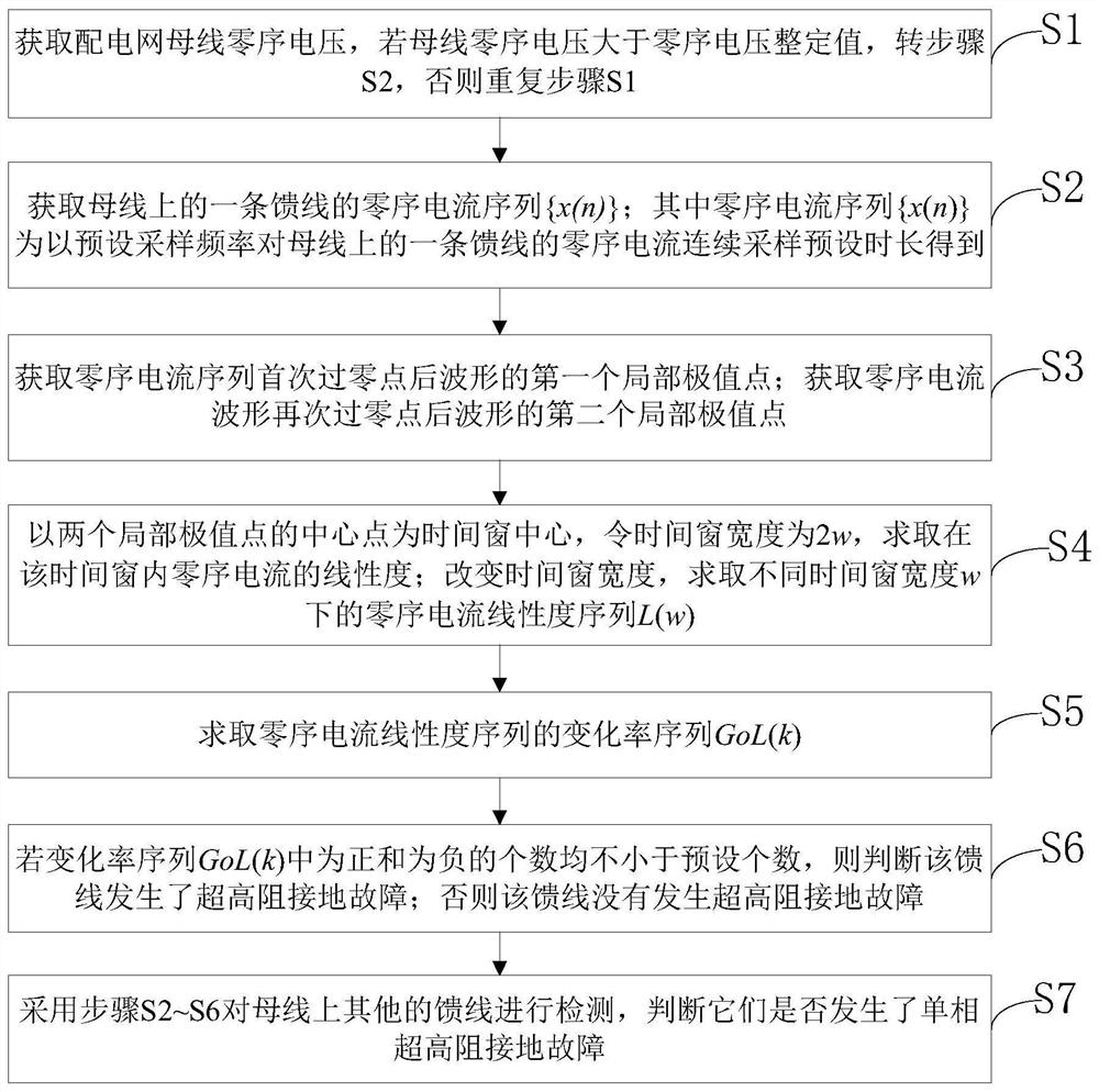
[0047] like figure 1 , figure 2 As shown, this embodiment provides a method for line selection of a high-impedance ground fault in a resonant ground distribution network, including:
[0048] Step S1: Obtain the zero-sequence voltage of the busbar of the distribution network. Since the zero-sequence voltage of the busbar is greater than the zero-sequence voltage setting value (5% of the rated value of the phase voltage in this embodiment), go to step S2.
[0049] Step S2: Obtain the zero-sequence current sequence {x(n)} of a feeder on the bus; where the zero-sequence current sequence {x(n)} is a feeder on the bus with a sampling frequency of 10kHz after a delay of 0.2 seconds The zero-sequence current is obtained by continuous sampling for 0.03 seconds, n=1, 2, 3,...,300.
[0050] Step S3: Obtain the first local extremum point of the waveform after the first zero-crossing point of the zero-sequence current sequence - the extremum point x(n 1 ), where n 1 is the sampling va...
Embodiment 2
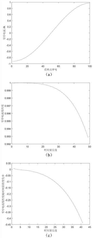
[0060] like figure 1 and image 3 As shown, the difference between this embodiment and embodiment 1 only lies in:
[0061] Step S3: Obtain the first local extreme point of the waveform after the first zero-crossing point of the zero-sequence current sequence—the maximum point x(n 1 ), where n 1 is the sampling value sequence number of the extremum point; obtain the second local extremum point of the waveform after the zero-sequence current waveform crosses the zero point again—the extremum point x(n 2 ), where n 2 is the sampling value sequence number of the extreme point; the zero-sequence current waveform between the two extreme points is as follows image 3 (a) shown.
[0062] Step S6: if image 3 The sequence GoL(k) shown in (c) is almost all positive, and the number of negative ones is less than 5, then it is judged that the line does not have a high-impedance ground fault (maybe the three-phase parameters of the line are unbalanced, or a low-impedance fault occurs...
Embodiment 3
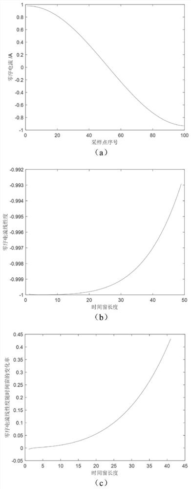
[0064] like figure 1 and Figure 4 As shown, the difference between this embodiment and embodiment 1 only lies in:
[0065] Step S3: Obtain the first local extremum point of the waveform after the first zero-crossing point of the zero-sequence current sequence - the extremum point x(n 1 ), where n 1 is the sampling value sequence number of the extremum point; obtain the second local extremum point of the waveform after the zero-sequence current waveform crosses the zero point again—the maxima point x(n 2 ), where n 2 is the sampling value sequence number of the extreme point; the zero-sequence current waveform between the two extreme points is as follows Figure 4 (a) shown.
[0066] Step S6: if Figure 4 The number of positive and negative numbers in the sequence GoL(k) shown in (c) is roughly equal, and they are all far greater than 5. It is judged that a high-impedance grounding fault has occurred on the line.
PUM
 Abstract
Description
Claims
Application Information
 - R&D
- Intellectual Property
- Life Sciences
- Materials
- Tech Scout
- Unparalleled Data Quality
- Higher Quality Content
- 60% Fewer Hallucinations
Browse by: Latest US Patents, China's latest patents, Technical Efficacy Thesaurus, Application Domain, Technology Topic, Popular Technical Reports.
© 2025 PatSnap. All rights reserved.Legal|Privacy policy|Modern Slavery Act Transparency Statement|Sitemap|About US| Contact US: help@patsnap.com


