
Time self-adaptive air system flow heat coupling method

An air system, flow-heat coupling technology, applied in instruments, electrical digital data processing, computer-aided design, etc., can solve problems such as errors, and achieve the effect of reducing research and development costs, taking into account calculation efficiency, and optimization of calculation accuracy

Pending Publication Date: 2021-11-30
NANJING UNIV OF AERONAUTICS & ASTRONAUTICS
View PDF0 Cites 0 Cited by
  • Summary
  • Abstract
  • Description
  • Claims
  • Application Information

AI Technical Summary

Problems solved by technology

[0004] However, in order to save computing resources in the above calculation method, the fluid domain is regarded as a quasi-steady state calculation. Applying this method to the thermal analysis of the air system may cause certain errors

Method used


Image

  • Time self-adaptive air system flow heat coupling method
  • Time self-adaptive air system flow heat coupling method
  • Time self-adaptive air system flow heat coupling method

Examples


Embodiment Construction

[0019] Embodiments of the invention are described in detail below, examples of which are illustrated in the accompanying drawings. The embodiments described below by referring to the figures are exemplary only for explaining the present invention and should not be construed as limiting the present invention.

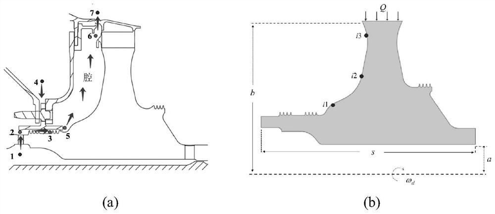
[0020] by figure 1 A typical engine air system configuration is shown as an example to illustrate the calculation method of the present invention. figure 1 (a) shows a schematic plan view of the structure of the turbine disk cavity of a real engine. The flow path of the air system is shown by the arrow. A stream of cold air is introduced from node 1 of the inter-shaft channel, and enters the front cavity of the turbine disk through the sealed grate teeth. chamber, the cooled turbine disk flows out from the flange seal to the outlet node 7. Another stream of cold air flows in from node 4 through the connecting gap of the stator, and enters the disk cavity after mixing w...


PUM


Abstract

The invention discloses a time-adaptive air system flow-heat coupling method, in flow-heat coupling calculation, heat conduction of a solid domain and flow of a fluid domain are both regarded as unsteady states, fluid domain parameters of a disc cavity system are calculated by using a one-dimensional transient network method, and heat conduction calculation of a two-dimensional solid domain is regarded as an unsteady state. On the basis of a traditional serial interleaving method, fluid-solid information interaction in a single coupling time step length is achieved, and the coupling time step length is automatically adjusted along with the number of iterations by using a proportional integral differential controller. The advantages of a traditional loose coupling calculation method and a traditional tight coupling calculation method are fused, and the calculation efficiency and the calculation precision are remarkably balanced.

Description

technical field [0001] The invention relates to a time-adaptive air system flow heat coupling method, in particular to an adaptive time step coupling calculation method combining one-dimensional transient air system calculation and two-dimensional solid domain temperature field heat conduction, belonging to the air system flow field of thermal computing. Background technique [0002] The thermal analysis of the air system needs to fully consider the heat transfer between the various components of the engine and the cold air and the influence of the temperature field of the components on the air system. Traditional thermal analysis is based on the completion of the air system design, using the air system data to calculate the temperature field of the hot end components. This design method ignores the interaction between the air system and thermal analysis components, and the calculation results are not accurate. In order to design the air system of the engine more accuratel...

Claims


Application Information

Patent Timeline
IPC IPC(8): G06F30/28G06F30/23G06F113/08G06F119/08G06F119/14
CPCG06F30/28G06F30/23G06F2113/08G06F2119/14G06F2119/08Y02T90/00
Inventor 郭纳贤毛军逵王磊潘进王飞龙
Owner NANJING UNIV OF AERONAUTICS & ASTRONAUTICS
Learn More