
Substation grounding wire mobile operation device and grounding wire connection method

A technology of mobile operation and grounding wire, applied in the direction of cable installation device, switch device, cable installation, etc., can solve the problems of dragging damage, grounding wire disorder, inconvenient storage, etc.

Active Publication Date: 2021-11-30
国网河南省电力公司超高压公司 +1
View PDF5 Cites 0 Cited by
  • Summary
  • Abstract
  • Description
  • Claims
  • Application Information

AI Technical Summary

Problems solved by technology

[0004] The purpose of the present invention is to provide a mobile substation grounding wire operation device and a grounding wire connection method in view of the problems in the prior art. Using the device to connect and move the grounding wire is flexible, applicable to various operating conditions, and solves the problem of the conventional grounding wire. During use, there are often problems such as messy lines, twisting, dragging damage, inconvenient use, and inconvenient storage

Method used


Image

  • Substation grounding wire mobile operation device and grounding wire connection method
  • Substation grounding wire mobile operation device and grounding wire connection method
  • Substation grounding wire mobile operation device and grounding wire connection method

Examples


Embodiment 1

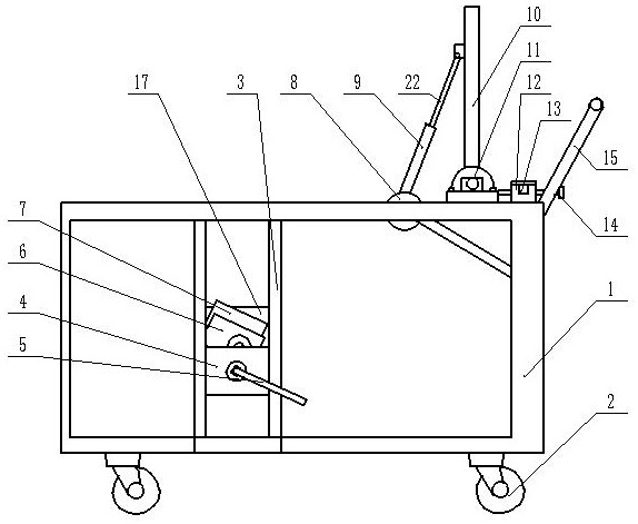
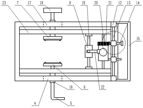
[0037] Such as figure 1 Shown is a schematic structural diagram of a substation grounding line mobile operation device provided by this implementation, figure 2 for figure 1 The schematic diagram of the top view of the structure, which includes a bracket 1, and the four corners of the bottom of the bracket 1 are respectively equipped with universal wheels 2 for easy movement, which not only makes the transportation of the ground wire more convenient, but also makes the suspension of the ground wire more secure. The two sides of the support 1 are respectively provided with two spaced vertical support rods 3, the support 1 is provided with a handle 15, and the two vertical support rods 3 are respectively provided with a ground wire take-up line The frame rotating device, the ground wire support device and the hydraulic rod lifting device for adjusting the ground wire support device are fixedly arranged on the support.

[0038] This embodiment discloses the detailed structure of...

Embodiment 2

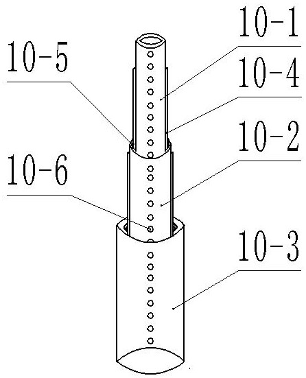
[0052] In order to solve the disadvantages in Embodiment 1, namely the non-adjustable length of the ground wire rod, in this implementation, the ground wire rod 10 is designed as an adjustable rod, including three telescopic tubes, respectively the first The telescopic cylinder 10-1, the second telescopic cylinder 10-2, and the third telescopic cylinder 10-3, the outer wall sides of the first telescopic cylinder 10-1 located at the innermost side are symmetrically provided with slider bars 10-4, and the adjacent The inner wall of the second telescopic cylinder 10-2 is provided with a matching chute 10-5 corresponding to the slider bar 10-4, and a plurality of uniform positioning holes 10-6 are arranged on the telescopic cylinder described in each section. The position of the positioning hole 10-6 is limited by the limit bolt, and the symmetrical two sides are set at the same time, so the stability is stronger. The ground wire operating rod is fixed to the upper end of the grou...


PUM


Abstract

The invention belongs to the technical field of substation ground wire operation devices, and particularly relates to a substation grounding wire mobile operation device and a grounding wire connection method. The device comprises a support, two vertical supporting rods arranged separately are arranged on the two side faces of the support respectively, a handle is arranged on the support, grounding wire take-up frame rotating devices are arranged on the two vertical supporting rods respectively, and a grounding wire supporting device and a hydraulic rod lifting device for adjusting the grounding wire supporting device are fixedly arranged on the support. When the device is used for grounding wire connection, movement is flexible, the device is suitable for various operation conditions, and the problems that a conventional grounding wire is often disordered, twisted, damaged by dragging, inconvenient to use and inconvenient to store in use are solved.

Description

technical field [0001] The invention belongs to the technical field of substation ground wire operating devices, and in particular relates to a substation ground wire mobile operating device and a ground wire connection method. Background technique [0002] The installation and disassembly of the ground wire is often involved in the switching operation. The suspension point of the ground wire of the 500kV substation equipment is too high. The corresponding 500kV ground wire operating rod is 7.5 meters long and weighs about 4kg. The three-in-one ground wire fixed on the ground wire hook It weighs up to 12kg, and it is difficult for the operation and maintenance personnel to grasp the balance of the ground wire operating rod with arm and wrist strength during the operation, so that 3-4 operators are required to cooperate and take a long time. They can only work with the aerial lift truck, but the arrangement It is a waste of manpower and material resources for the aerial lift ...

Claims


Application Information

Patent Timeline
Patent Type & Authority Applications(China)
IPC IPC(8): H02G1/00H02B3/00
CPCH02G1/00H02B3/00
Inventor 宋晓军陈若冰刘奇峰盛耀巍石超赵明康张秋霞赵艳珍
Owner 国网河南省电力公司超高压公司
Learn More