Wire cutting device for electronic components

A technology of electronic components and cutting devices, which is applied in the field of wire cutting devices for electronic components, can solve the problems of slow speed, inconsistent length of wires, cumbersome wire operation, etc., and achieve the effect of improving efficiency

Active Publication Date: 2022-05-03
深圳市集电通实业有限公司
View PDF7 Cites 0 Cited by
  • Summary
  • Abstract
  • Description
  • Claims
  • Application Information

AI Technical Summary

Problems solved by technology

[0004] In order to overcome the cumbersome and slow operation of manually cutting the wires, the hand of the operator is easily injured when cutting the wires with scissors, and the lengths of the cut wires are inconsistent. The technical problem to be solved is: to provide an easy-to-use, The speed za is fast, the length of the cut wire is consistent, and the wire cutting device for electronic components with high safety factor

Method used


Image

  • Wire cutting device for electronic components
  • Wire cutting device for electronic components
  • Wire cutting device for electronic components

Examples


Embodiment 1

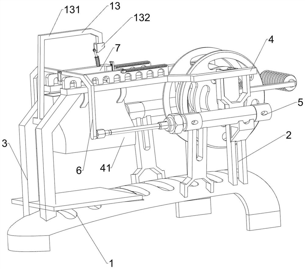
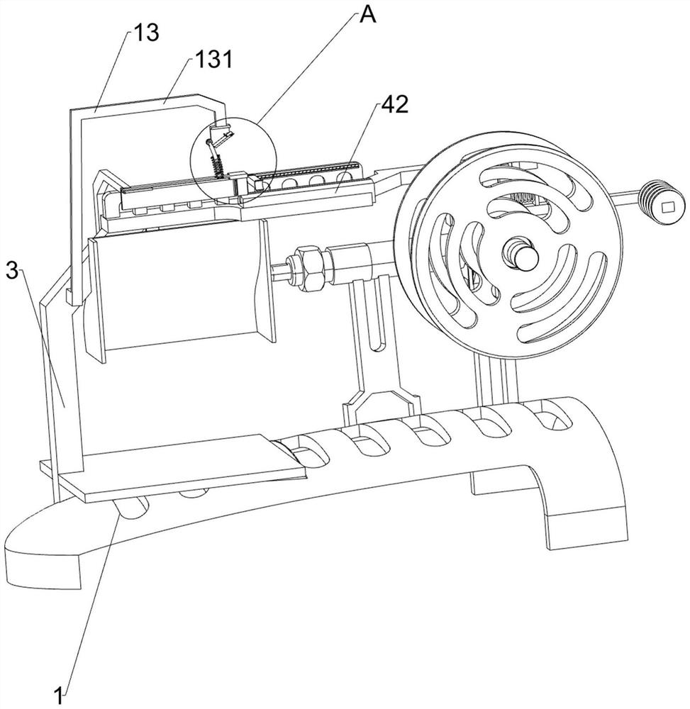
[0028] A wire cutting device for electronic components, such as figure 1 , figure 2 and Figure 4 As shown, it includes a base 1, a first leg 2, a second leg 3, a mounting plate 4, a collecting hopper 41, a groove plate 42, a cylinder 5, a sliding frame 6, a housing 7, a cutter 8, and a cutting mechanism 9 And the pay-off mechanism 10, two first legs 2 are installed on the right side of the top of the base 1, two second legs 3 are installed on the left side of the top of the base 1, two first legs 2 and two second legs Mounting plate 4 is installed on 3, collecting hopper 41 is installed on the left side of mounting plate 4, and the groove plate 42 that is used for wire sliding is installed on the top of mounting plate 4 right side, and first support leg 2 both sides are provided with cylinder 5, and cylinder 5 is Horizontally installed, a sliding frame 6 is fixedly installed on the telescopic rod of the cylinder 5, and a housing 7 is installed on the sliding frame 6. The ...

Embodiment 2

[0033] On the basis of Example 1, such as figure 1 , figure 2 , image 3 , Figure 5 , Figure 6 , Figure 7 , Figure 8 and Figure 9 Shown, also include feeding mechanism 11, feeding mechanism 11 includes lower rack 111, clamping plate 112, upper rack 113, first spring 114, drive inclined block 115, clamping plate 117, second spring 118, gear 119 and The contact block 1110 has a mounting groove 1121 on the front part of the right side of the housing 7, and the right side of the mounting groove 1121 is slidably installed with the lower rack 111, and the left side of the mounting groove 1121 is slidably installed with the upper rack 113 and the lower rack. 111 and upper rack 113 are alternately arranged, the length of lower rack 111 is longer than that of upper rack 113, and the upper end of lower rack 111 protrudes from housing 7, both lower rack 111 and upper rack 113 are L-shaped, and the lower rack 111 is L-shaped. 111 and the right side of the upper rack 113 are f...

Embodiment 3

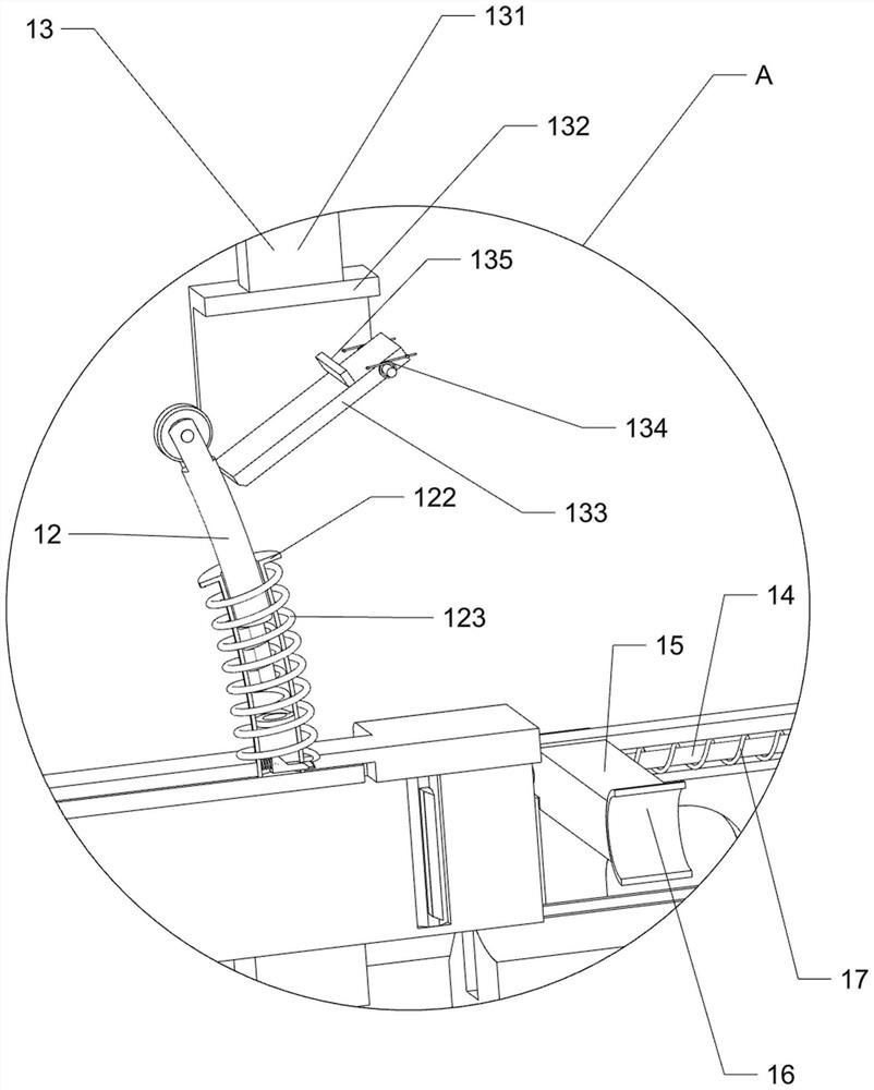
[0040] On the basis of embodiment 1 and embodiment 2, such as figure 2 , image 3 and Figure 4 Shown, also comprise guide rod 14, slide plate 15, sleeve ring 16 and the 6th spring 17, special-shaped inclined plate 94 right sides are equipped with guide rod 14, slide type is installed with slide plate 15 on the guide rod 14, slide plate 15 middle parts are equipped with the sleeve ring 16 that is used for guiding wire, are connected with the 6th spring 17 between sliding plate 15 and special-shaped inclined plate 94, and the 6th spring 17 is wound on the guide rod 14.

[0041] Also comprise movable frame 18, riser 19 and the 7th spring 20, limit frame 101 middle part right side sliding type is equipped with movable frame 18, movable frame 18 is used for limiting the movement of rolling shaft 103, vertical frame 18 is installed with A seventh spring 20 is connected between the plate 19 , the vertical plate 19 and the limit frame 101 .

[0042] The operator puts the wire int...


PUM


Abstract

The invention relates to a wire cutting device, in particular to a wire cutting device for electronic components. The technical problem to be solved is to provide a wire cutting device for electronic components that is easy to use, has a fast cutting wire speed, has the same length of cut wires, and has a high safety factor. A wire cutting device for electronic components, including a base, a first leg, a second leg, a mounting plate, a collecting hopper, a slot plate, a cylinder, a sliding frame, a housing, a cutter, a cutting mechanism, and a wire-releasing mechanism One side of the base is symmetrically fixed with a first leg, the other side of the base is symmetrically fixed with a second leg, and the mounting plate is fixedly connected with the first leg and the second leg. The invention drives the housing and the cutter to move left and right through the cylinder, and under the action of the special-shaped inclined plate, the wire pulled to the left can be cut off.

Description

technical field [0001] The invention relates to a wire cutting device, in particular to a wire cutting device for electronic components. Background technique [0002] Conductor refers to the material used for wire and cable. In industry, it also refers to wire. It is generally made of copper or aluminum, and it is also made of silver wire, which is used to conduct current or conduct heat. At present, when electronic components are assembled, a large number of wires need to be used to connect the electronic components to the main board. Now the operator usually holds scissors in one hand and pulls out the wires in the other hand, and then cuts the wires to the same size. length. The operation of manually cutting the wires is tedious and slow, and the operator's hands are easily injured when using scissors to cut the wires, and the lengths of the cut wires are inconsistent. [0003] In summary, it is now necessary to design a wire cutting device for electronic components tha...

Claims


Application Information

Patent Timeline
Patent Type & Authority Patents(China)
IPC IPC(8): B21F11/00B21F23/00
CPCB21F11/00B21F23/00
Inventor 洪晓丹
Owner 深圳市集电通实业有限公司
Why Eureka
Try Eureka