Forage processing device for livestock breeding
A processing device and forage technology, which is applied in application, feed, agricultural machinery and tools, etc., can solve the problems of increasing the labor intensity of animal husbandry, failing to feed livestock, and affecting processing efficiency, so as to reduce the labor intensity of workers, reduce labor consumption, Reduce the effect of repeated handling
- Summary
- Abstract
- Description
- Claims
- Application Information
AI Technical Summary
Problems solved by technology
Method used
Image
Examples
Embodiment 1
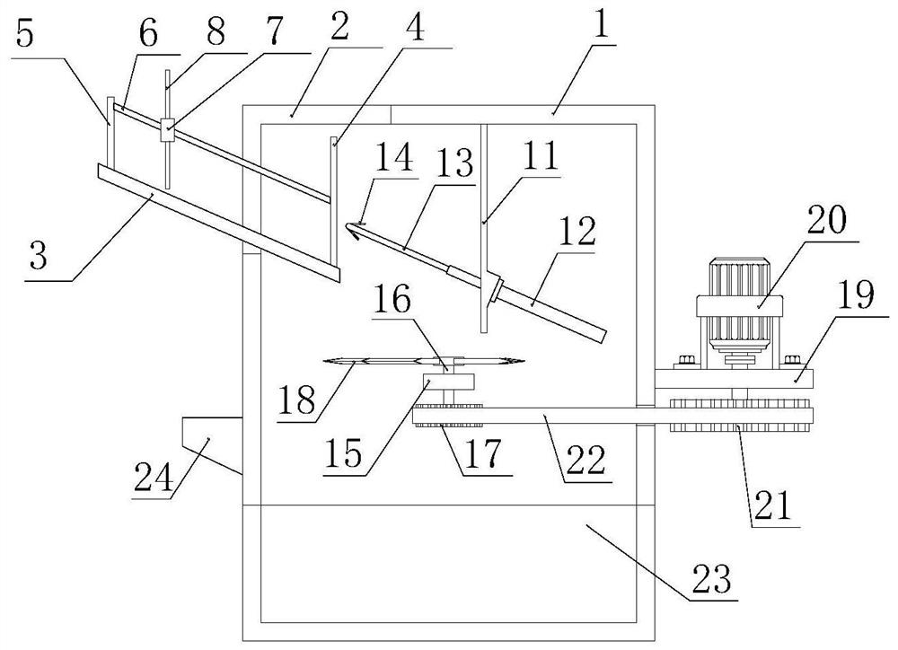
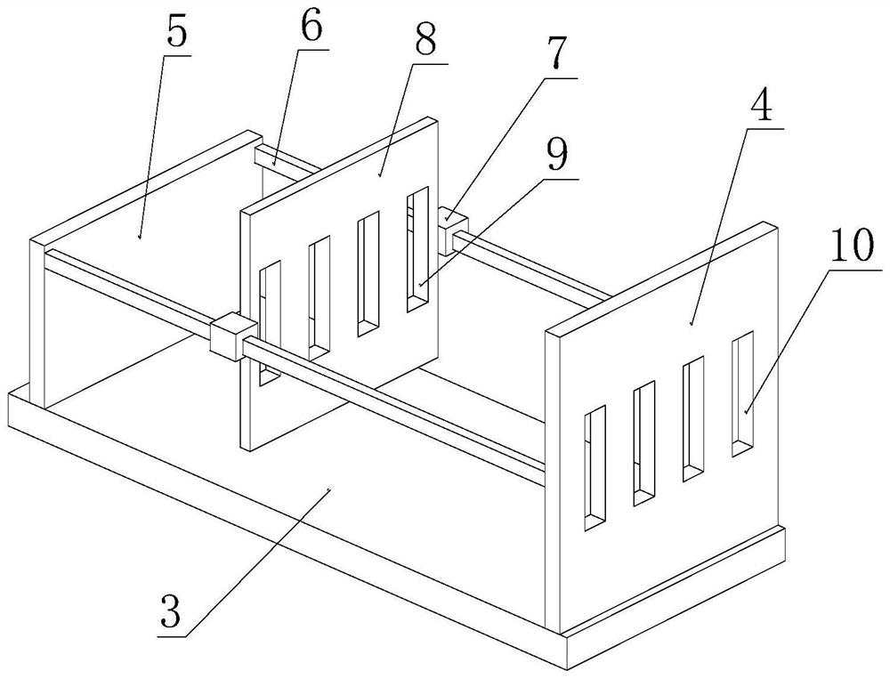
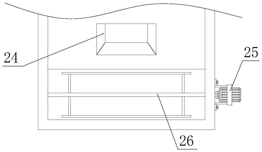
[0030] Such as Figure 1-4 As shown, the present specific embodiment adopts the following technical solutions: a pasture processing device for animal husbandry, comprising a casing 1, a top side of the casing 1 has a No. 1 feed port 2, and the bottom of the No. 1 feed port 2 The placement plate 3 is fixedly connected, and the placement plate 3 is inclined to the inside of the box body 1 with an inclination angle greater than 30 degrees. One end top is fixedly connected with a No. 1 support plate 5, and an extrusion plate 8 is movably connected between the No. 1 support plate 5 and the baffle plate 4, and an insertion rod 13 is provided at a position opposite to the baffle plate 4 inside the box body 1 .
[0031] Wherein, the inner top of the box body 1 is fixedly connected with the No. 2 support plate 11, and the bottom of the No. 2 support plate 11 is fixedly connected with the electric telescopic rod 12 on the side away from the placement plate 3, and the output end of the e...
Embodiment 2
[0039] In the scheme of embodiment 1, the haystack only relies on the gravity of the extrusion plate 8 to be limited between the extrusion plate 8 and the baffle plate 4. When the insertion rod 13 is inserted in the haystack, under the force of the insertion rod 13, The extruding plate 8 may slide towards the side of the No. 1 supporting plate 5, so that the efficiency of pulling grass is reduced.
[0040] Therefore, in this embodiment, a limiting mechanism for restricting the sliding of the pressing plate 8 toward the side of the first supporting plate 5 is also provided between the baffle plate 4 and the No. 1 supporting plate 5 . Such as Figure 5 As shown, the limit mechanism includes two fixed rods 28 arranged above the two sliding rods 6, and the two ends of the fixed rods 28 are respectively fixed on the side walls of the opposite sides of the baffle plate 4 and the No. 1 support plate 5, and the two fixed rods The rods 28 are all rotatably provided with a plurality of...
Embodiment 3
[0044] In this embodiment, a limiting mechanism is also provided. The limiting mechanism in this embodiment is different from that in Embodiment 2. In this embodiment, two fixed rods 28 are also rotatably provided with a plurality of The limit rod 29 is differently, such as Figure 6 As shown, the fixed rod 28 is provided with a plurality of limit grooves 31, and the plurality of limit rods 29 are arranged in the limit grooves 31 through the rotation shaft 30 in one direction. In the natural state, the limit rods 29 are close to One side fits on the groove wall of the limiting groove 31, and the rotation of the limiting rod 29 is limited. There is room for avoidance.
[0045] That is to say, in embodiment 1, the unidirectional rotation of the limiting rod is realized by setting the structure of the limiting rod, and in this embodiment, the unidirectional rotation of the limiting rod is realized by setting the limiting groove.
[0046] During the use of the limit mechanism in...
PUM
 Abstract
Description
Claims
Application Information
 - R&D
- Intellectual Property
- Life Sciences
- Materials
- Tech Scout
- Unparalleled Data Quality
- Higher Quality Content
- 60% Fewer Hallucinations
Browse by: Latest US Patents, China's latest patents, Technical Efficacy Thesaurus, Application Domain, Technology Topic, Popular Technical Reports.
© 2025 PatSnap. All rights reserved.Legal|Privacy policy|Modern Slavery Act Transparency Statement|Sitemap|About US| Contact US: help@patsnap.com


