A wooden handle pressing anti-skid device
A kind of anti-skid pattern and handle technology, applied in the direction of wood compression, manufacturing tools, wood processing utensils, etc., can solve the problem of wood chips being difficult to clean, and achieve the effect of reducing manual operation.
- Summary
- Abstract
- Description
- Claims
- Application Information
AI Technical Summary
Problems solved by technology
Method used
Image
Examples
Embodiment 1
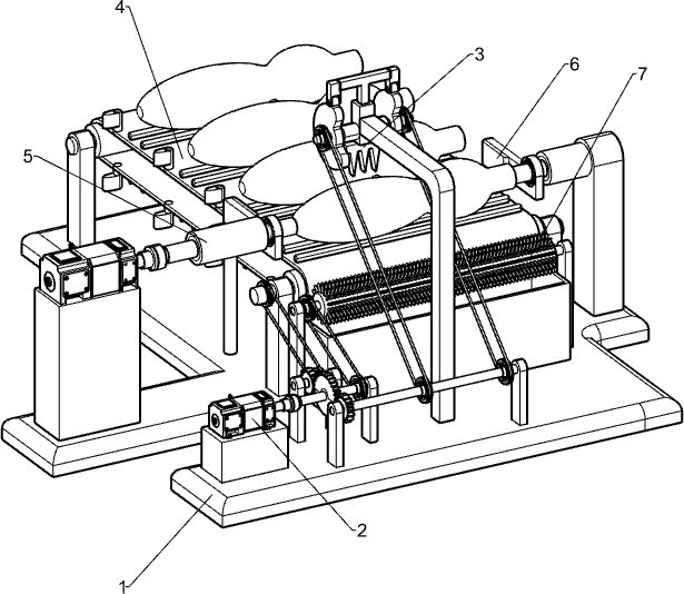
[0041] A wooden handle pressing anti-skid device, such as figure 1 As shown, it includes a base 1, a driving motor 2, an anti-skid printing mechanism 3, an intermittent transport mechanism 4 and a shaft moving mechanism 5. The driving motor 2 is installed on the left front side of the base 1, and the anti-skid printing The anti-slip pattern printing mechanism 3 is connected with the driving motor 2, the middle part of the base 1 is provided with an intermittent transport mechanism 4, the intermittent transport mechanism 4 is connected with the anti-slip pattern printing mechanism 3, and the left and right sides of the front of the base 1 are installed with Shaft moving mechanism 5.
[0042]Place the wooden handle on the parts of the intermittent transport mechanism 4, then start the parts in the drive motor 2 and the rotating shaft moving mechanism 5, the output shaft of the drive motor 2 drives the parts in the anti-slip pattern printing mechanism 3 to rotate, when the anti-s...
Embodiment 2
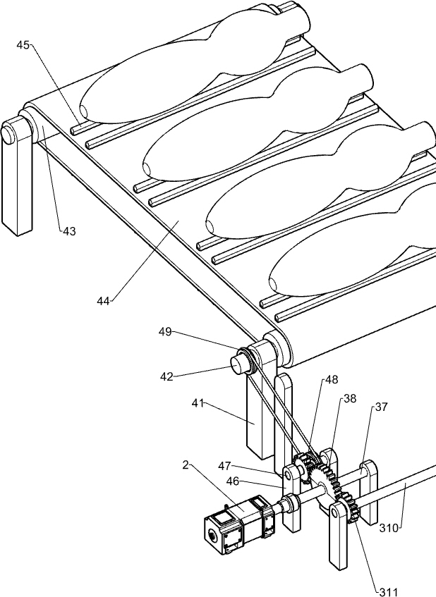
[0044] Specifically, as Figure 1-3 As shown, the anti-slip pattern printing mechanism 3 includes a first bracket 31, a sliding sleeve 32, a T-shaped connecting rod 33, a roller 34, a pattern cutter 35, a cam 36, a first rotating shaft 37, a half-tooth bull gear 38, a second Support 39, second rotating rod 310, first full-toothed pinion 311 and first belt assembly 312, base 1 middle part front side is provided with first support 31, first support 31 upper rear side is equipped with sliding sleeve 32, sliding sleeve T-shaped connecting rod 33 is connected in sliding type in 32, and is connected by elastic member between sliding sleeve 32 and T-shaped connecting rod 33, and T-shaped connecting rod 33 bottom left and right sides are all provided with roller 34, and T-shaped connecting rod 33 bottoms middle Printing cutter 35 is installed, the left and right sides of the lower part of sliding sleeve 32 are provided with cam 36 through round bar rotation, and cam 36 is in contact w...
Embodiment 3
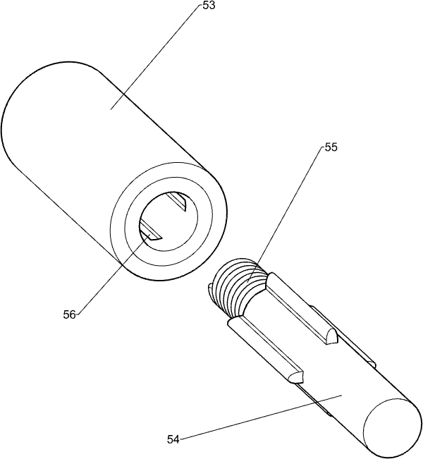
[0049] In particular, refer to figure 1 and Figure 4-6 As shown, the rotating shaft moving mechanism 5 includes a fifth support frame 51, a high-speed motor 52, a rotating cylinder 53, a cross-shaped rotating shaft 54 and a spring 55. The fifth support frame 51 is installed on the right front side of the base 1, and a high Rotating speed motor 52, on the output shaft of high rotating speed motor 52 and on the left side of the top of the fifth support frame 51, rotating drum 53 is equipped with rotating drum 53 and the fifth supporting frame 51, and rotating drum 53 inwall is provided with four A chute 56, slidingly provided with a cross-shaped rotating shaft 54 in the chute 56, the cross-shaped rotating shaft 54 is located directly above the third rotating shaft 42 on the front side, and a spring 55 is connected between the cross-shaped rotating shaft 54 and the rotating cylinder 53.
[0050] Put the wooden handle on the anti-skid bar 45, start the drive motor 2 and ...
PUM
 Abstract
Description
Claims
Application Information
 - R&D
- Intellectual Property
- Life Sciences
- Materials
- Tech Scout
- Unparalleled Data Quality
- Higher Quality Content
- 60% Fewer Hallucinations
Browse by: Latest US Patents, China's latest patents, Technical Efficacy Thesaurus, Application Domain, Technology Topic, Popular Technical Reports.
© 2025 PatSnap. All rights reserved.Legal|Privacy policy|Modern Slavery Act Transparency Statement|Sitemap|About US| Contact US: help@patsnap.com


