
Middle and rear floor framework

A rear floor and floor technology, which is applied in the field of vehicles, can solve the problems of low overlap between the beam and the threshold, difficult to achieve the collision star, and the beam cannot be used universally.

Pending Publication Date: 2021-12-03
ZHEJIANG GEELY HLDG GRP CO LTD +1
View PDF0 Cites 1 Cited by
  • Summary
  • Abstract
  • Description
  • Claims
  • Application Information

AI Technical Summary

Problems solved by technology

[0003] However, for pure electric vehicles, the battery is generally arranged under the front middle floor, between the battery pack installation beam and the floor, and in order to meet the requirements of the cruising range, it is necessary to arrange as many power batteries as possible to ensure the rigidity and strength of the battery pack installation point. , the size of the cavity formed by the battery pack installation beam and the floor needs to be as large as possible, so the floor of the electric vehicle needs to be arranged on the top, and the downward movement is severely restricted
[0004] The battery pack installation beam and the floor are both supported by the threshold, so there is a certain drop between the beam and the threshold, and the overlap between the beam and the threshold is low, making it difficult to achieve a star collision.
In addition, the force transmission path of the front impact will basically transmit the force through the middle longitudinal beam and the sill beam. Generally, the beams in this area cannot be used universally.

Method used


Image

  • Middle and rear floor framework
  • Middle and rear floor framework
  • Middle and rear floor framework

Examples


Embodiment 1

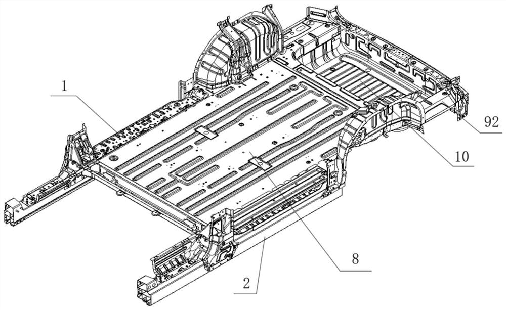
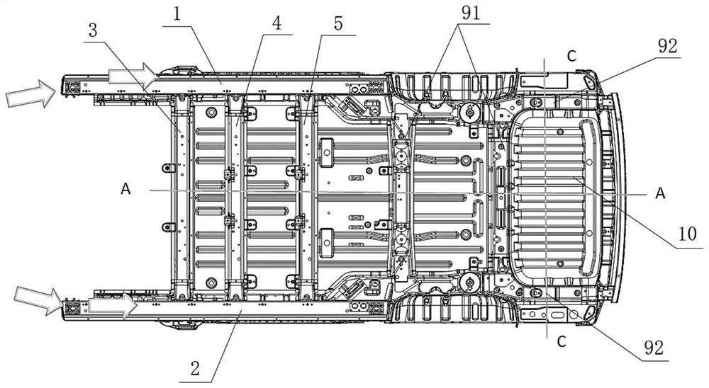
[0044] Such as figure 1 As shown, this embodiment provides a middle and rear floor structure, including a flat floor 8, a rear floor 9, a seat well 10, a middle floor frame structure and a battery pack 7, and the middle floor frame structure includes a beam assembly and a longitudinal beam assembly , the battery pack 7 is installed below the beam assembly, the flat floor 8 is installed above the beam assembly, the flat floor 8, the rear floor 9 and the seat pit 10 are connected in sequence, the beam assembly, the battery pack 7, the flat floor 8, and the rear floor 9 and the seat well 10 are supported by the stringer assembly.

[0045] The flat floor 8 is used for installing the second row of seats and the third row of seats, and the seat well 10 is used for installing the fourth row of seats.

[0046] Preferably, a seat long slide rail is laid on the upper surface of the flat floor 8 . Laying long seat slide rails can realize the common rail linkage of the second row and th...


PUM


Abstract

The invention relates to a middle and rear floor framework which comprises a flat floor, a rear floor, a seat pit, a middle floor frame type structure and a battery pack, the middle floor frame type structure comprises a cross beam assembly and a longitudinal beam assembly, the battery pack is installed below the cross beam assembly, the flat floor is installed above the cross beam assembly, the flat floor, the rear floor and the seat pit are sequentially connected, and the cross beam assembly, the battery pack, the flat floor, the rear floor and the seat pit are all supported by the longitudinal beam assembly. Compared with the prior art, the lightweight and universal design of the floor is realized; large space and high performance are realized, and the rigidity of the whole vehicle is enhanced by utilizing the structural strength of the battery; the rear flat floor and the seat can be turned into the pit; and the modular design has the advantages of deformability of different vehicle types and the like.

Description

technical field [0001] The invention relates to the field of vehicles, in particular to a middle and rear floor structure. Background technique [0002] In the middle and rear floor structure of the car body, generally the middle floor and the rear floor cannot be flush, and the middle floor beams are arranged in the car, in order to ensure that the whole vehicle can achieve ENCAP and CNCAP five-star safety goals, especially for side collisions And the column collision, the door sill bears the maximum force bearing, and the cross beam in the car bears the force transmission. [0003] However, for pure electric vehicles, the battery is generally arranged under the front middle floor, between the battery pack installation beam and the floor, and in order to meet the requirements of the cruising range, it is necessary to arrange as many power batteries as possible to ensure the rigidity and strength of the battery pack installation point. Therefore, the size of the cavity form...

Claims


Application Information

Patent Timeline
Patent Type & Authority Applications(China)
IPC IPC(8): B62D25/20B60K1/04
CPCB62D25/20B60K1/04B60K2001/0438
Inventor 南圣良于童张羽翼高兴郑楚强陈春龙
Owner ZHEJIANG GEELY HLDG GRP CO LTD
Learn More