
Power supply cable winding device

A winding device, a technology for electric cables, applied in the directions of transportation and packaging, transportation of filamentous materials, thin material processing, etc., can solve the problems of cleaning, inability to realize cables, etc., to avoid being damaged, avoid oxidation damage, and facilitate The effect of protecting the cable

Inactive Publication Date: 2021-12-03
滕智杰
View PDF1 Cites 0 Cited by
  • Summary
  • Abstract
  • Description
  • Claims
  • Application Information

AI Technical Summary

Problems solved by technology

[0006] Aiming at the deficiencies of the prior art, the present invention provides a power supply cable winding device, which solves the problem that the device cannot clean the cable when winding the cable, improves the winding efficiency, and effectively protects the The surface of the cable prevents the cable from being worn out, realizes the purpose of pretreatment of the cable before winding, straightens the power supply cable in advance, and effectively prevents the cable from being entangled and knotted before winding

Method used


Image

  • Power supply cable winding device
  • Power supply cable winding device
  • Power supply cable winding device

Examples


Embodiment 1

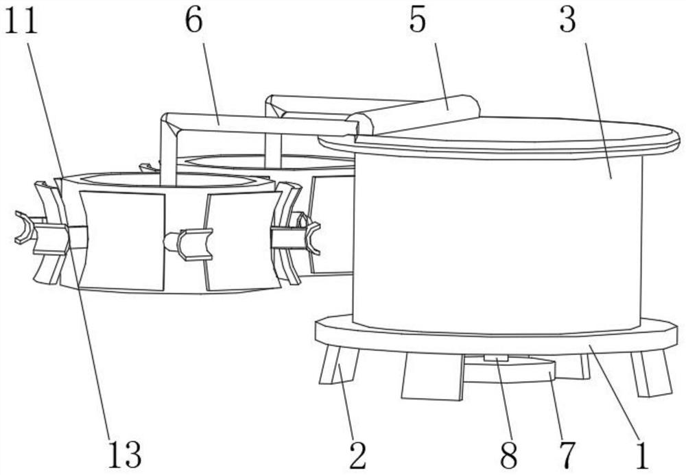
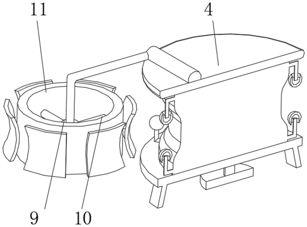
[0032] see Figure 1-4 , the present invention provides a technical solution: a power supply cable winding device, including a bottom plate 1, the bottom of the bottom plate 1 is evenly installed with a bottom support seat 2, and the top of the bottom plate 1 is rotatably connected to a reel 3, and the reel 3 The end away from the bottom plate 1 is fixedly connected with a top cover 4, the side of the top cover 4 away from the reel 3 is fixedly connected with a mounting column 5, and the side of the mounting column 5 is symmetrically connected with a fixed column 6, and the bottom plate 1 is close to the bottom support seat 2 A drive motor 7 is installed on one side of the drive motor 7, and the output end of the drive motor 7 is rotatably connected to a rotating shaft 8. The end of the fixed column 6 away from the mounting column 5 is provided with a limit block 9, and the outer side of the limit block 9 is provided with a support connecting rod. 10. The end of the supporting...

Embodiment 2

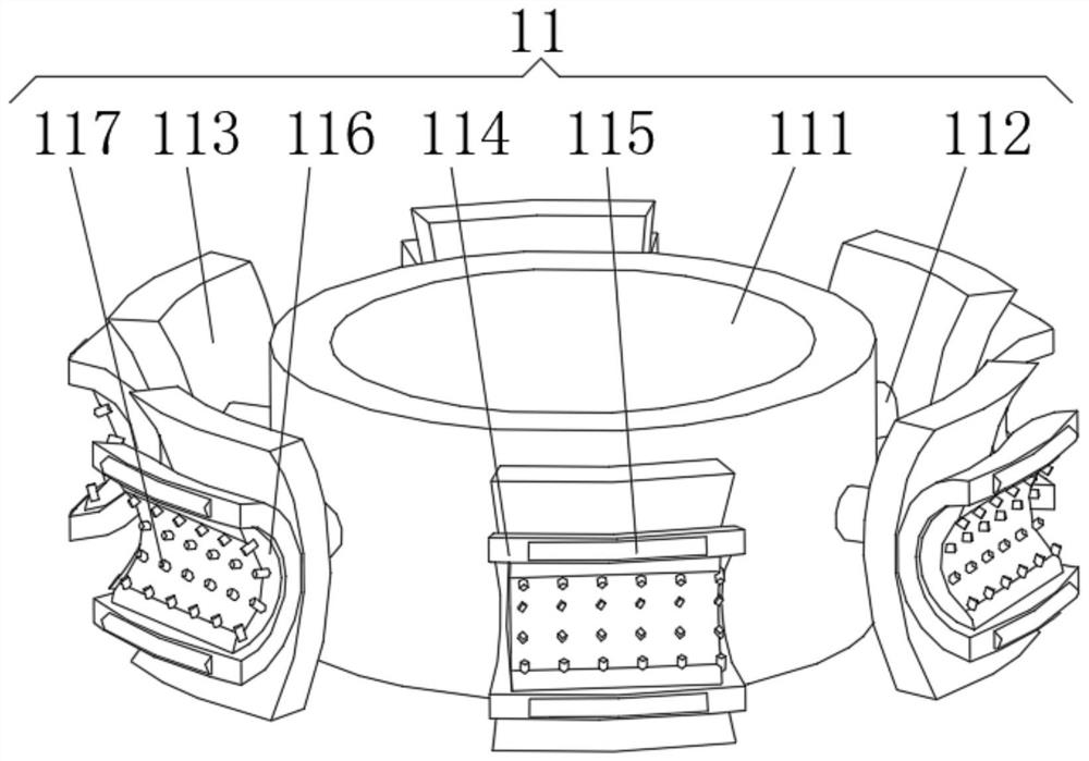
[0040] see Figure 1-6 , the present invention provides a technical solution: on the basis of Embodiment 1, an inflator 12 is installed inside the cleaning device 11, the air intake end of the air bag 116 is connected with an air intake pipe 14, and the end of the air intake pipe 14 away from the air bag 116 runs through the arc Shaped contact frame 114.

[0041] The inflatable device 12 includes a material storage frame 121, one side of the material storage frame 121 is fixedly connected with the arc-shaped contact frame 114, and the inside of the material storage frame 121 is provided with a solid cavity 122 and a liquid cavity 123, and the solid cavity 122 and the liquid cavity 123 pass through the flow The valve 124 communicates, and one side of the solid chamber 122 communicates with the intake pipe 14 .

[0042] A control rod 125 is installed on one side of the flow valve 124, and the top of the liquid chamber 123 is communicated with a feed pipe 126. The interior of th...


PUM


Abstract

The invention discloses a power supply cable winding device which comprises a bottom plate, wherein bottom supporting seats are uniformly mounted at the bottom of the bottom plate; a winding reel is rotationally connected to the top of the bottom plate; a top cover is fixedly connected to the end, away from the bottom plate, of the winding reel; a mounting column is fixedly connected to the side, away from the winding reel, of the top cover; fixing columns are symmetrically connected to one side of the mounting column; a driving motor is mounted on the side, close to the bottom supporting base, of the bottom plate; the output end of the driving motor is rotationally connected with a rotating shaft; the ends, away from the mounting column, of the fixing columns are sleeved with limiting blocks; the limiting blocks are sleeved with supporting connecting rods; cleaning devices are fixedly connected to the ends, away from the limiting blocks, of the supporting connecting rods. The invention relates to the technical field of cable winding. According to the power supply cable winding device, the purpose of cleaning the cable before winding is achieved, the winding efficiency is improved, the surface of the cable is effectively protected, and the cable is prevented from being abraded.

Description

technical field [0001] The invention relates to the technical field of cable winding, in particular to a power supply cable winding device. Background technique [0002] The power supply cable is a wire product used to transmit electric (magnetic) energy, information and realize the conversion of electromagnetic energy. In the broad sense, wires and cables are also referred to as cables for short. In the narrow sense, cables refer to insulated cables, which can be defined as: a collection composed of the following parts; one or more insulated cores, and their respective possible coatings. The protective layer and the outer sheath, the cable can also have an additional uninsulated conductor, and the power supply cable usually needs to be reeled for the convenience of transportation and use, although the existing reeling device can realize the rewinding of the power supply cable , but mostly by setting the corresponding reel and replacing the reel with different specification...

Claims


Application Information

Patent Timeline
Patent Type & Authority Applications(China)
IPC IPC(8): B65H54/70B65H71/00B65H54/44B21F1/02
CPCB65H54/702B65H71/007B65H54/44B21F1/02B65H2701/34
Inventor 滕智杰
Owner 滕智杰
Learn More