Heating system with photoelectric heat source

A heating and photoelectric technology, applied in solar heating systems, energy industries, heating devices, etc., can solve the problems of low energy utilization, low thermal efficiency, hidden dangers of electric leakage, etc., and achieve the effect of saving building installation costs and a high degree of automation

Inactive Publication Date: 2004-02-04
李达安 +1
View PDF0 Cites 0 Cited by
  • Summary
  • Abstract
  • Description
  • Claims
  • Application Information

AI Technical Summary

Problems solved by technology

[0002] At present, most of the heating equipment for industrial and civil buildings use boilers that use coal, gas or oil as energy sources. The disadvantages of such equipment are well known, such as pollution to the atmospheric environment during combustion, fuel transportation, storage, emissions and many other inconveniences. Although this type of equipment has been improved many times, the energy utilization rate is low and the fuel is wasted a lot. There is a danger of causing a catastrophe, and the construction of boiler rooms and fuel storage will not only consume a lot of manpower, material resources, and financial resources, but also take up a lot of precious land.
The electric heating and heating equipment scattered in the users, such as small heat storage electric boilers, electric heaters, air conditioners, heaters, electric water heaters, etc., cannot be widely used because of their low thermal efficiency, large power consumption, and high price. accepted by users
At present, the product with advanced heating and heating performance in the world is a regenerative electric boiler produced in the United States. The heating element they use is resistance wire or heat pipe. The electric heat conversion rate is 68.4%. The average life of the electric heat pipe is 1000 hours. It needs to be replaced every heating season. Because the electric heating tube is in direct contact with water, there is a hidden danger of electric leakage. The solution is to rely on a complex electrical protection system to control it. The current price of this equipment is very high, and it is difficult to popularize it.

Method used


Image

  • Heating system with photoelectric heat source
  • Heating system with photoelectric heat source
  • Heating system with photoelectric heat source

Examples


specific Embodiment

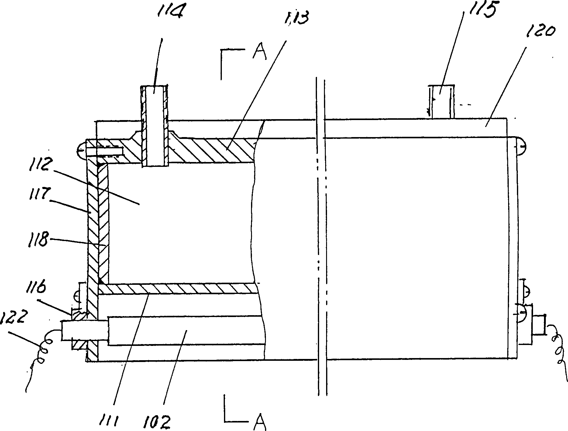
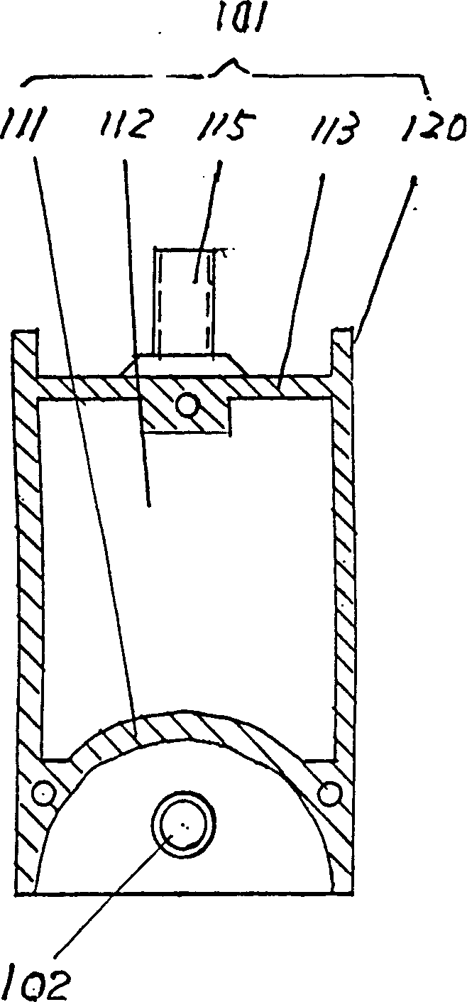
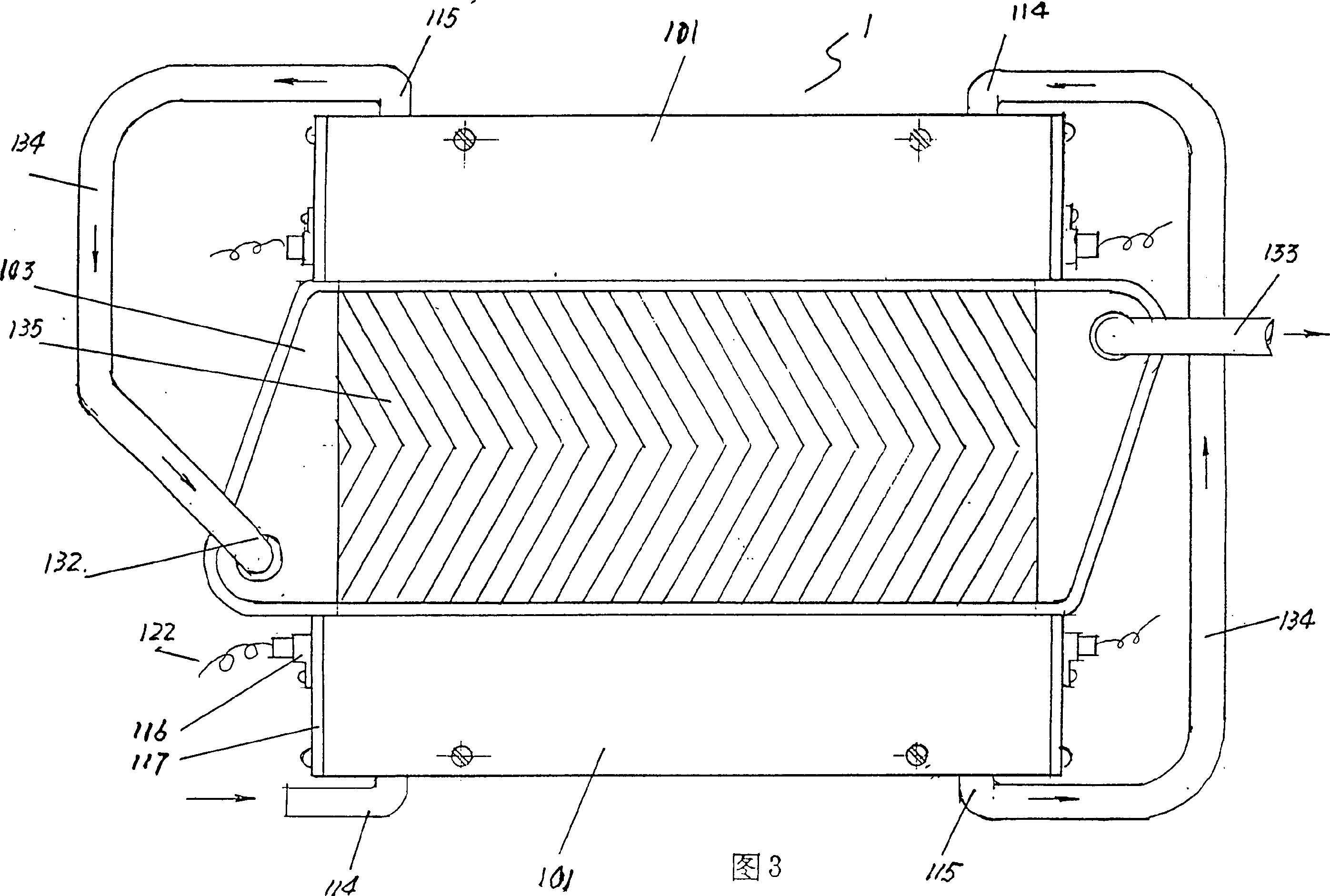
[0071] The structure of the 18KW photoelectric heating unit manufactured according to the above principle is as follows: it consists of two rows of photoelectric heating units (each 15 units), each with a heat exchanger between the upper and lower groups, and the circulating water is reflected by the lower row. The internal cavity flows to the upper reflector internal cavity and then flows through the heat exchanger. The heat medium heats up by 25°C, and the flow rate is 526 liters / hour. According to the heating standard in Beijing, the average indoor temperature is 18°C, and the minimum outdoor temperature is -16°C. The area that can be heated 306 square meters.

[0072] Performance comparison between photoelectric heating host and American regenerative electric boiler

[0073] the power

KW

heat up

25°C

flow

L / hour

Heating area

Annual operating fee

Yuan / M 2

3

electric h...


PUM


Abstract

The heating system consists of photoelectric heating machine, heat accumulating tank, control cabinet and heat medium circulating pipe system. The photoelectric heating machine consists of several photoelectric heating units comprising light condensing reflector with smooth concave reflecting surface, quartz lamp tube fixed at the focus point of the reflector, and heat exchanger installed in the position irradiated by the reflected light and with water inlet pipe connected to the water outle tof the condensing reflector cooling water. The present invention has zero pollution, no exchaust, high efficiency, saving in energy and other advantages and may be used in heating for industry and household.

Description

technical field [0001] The invention relates to industrial and building heating and heating engineering, in particular to a heating and heating system using photoelectricity as a heat source. Background technique [0002] At present, most of the heating equipment for industrial and civil buildings use boilers that use coal, gas or oil as energy sources. The disadvantages of such equipment are well known, such as pollution to the atmospheric environment during combustion, fuel transportation, storage, emissions and many other inconveniences. Although this type of equipment has been improved many times, the energy utilization rate is low and the fuel is wasted a lot. There is the danger of causing a catastrophe, and the construction of boiler rooms and fuel storage will not only consume a lot of manpower, material and financial resources, but also take up a lot of valuable land. The electric heating and heating equipment scattered in the users, such as small heat storage elec...

Claims


Application Information

Patent Timeline
Patent Type & Authority Patents(China)
IPC IPC(8): F24H1/18F24S23/74
CPCY02B10/20Y02E10/45Y02E10/40Y02P80/20
Inventor 李达安李勇
Owner 李达安
Why Eureka
Try Eureka