Eureka AIR delivers breakthrough ideas for toughest innovation challenges, trusted by R&D personnel around the world.

Single-driving-source push-pull composite ultrahigh-pressure coring device and grabbing and loosening method

A coring device, source push-pull technology, applied in the direction of extracting the undisturbed core device, earth cube drilling and mining, etc., can solve the problem of large volume

Pending Publication Date: 2021-12-03
SHENZHEN UNIV
View PDF1 Cites 0 Cited by
  • Summary
  • Abstract
  • Description
  • Claims
  • Application Information

AI Technical Summary

Problems solved by technology

Although the connecting rod arm of this patent is a mechanical structure, it has a large volume and is not suitable for an environment with a narrow working space and a large pulling force

Method used


Image

  • Single-driving-source push-pull composite ultrahigh-pressure coring device and grabbing and loosening method
  • Single-driving-source push-pull composite ultrahigh-pressure coring device and grabbing and loosening method
  • Single-driving-source push-pull composite ultrahigh-pressure coring device and grabbing and loosening method

Examples


Embodiment 1

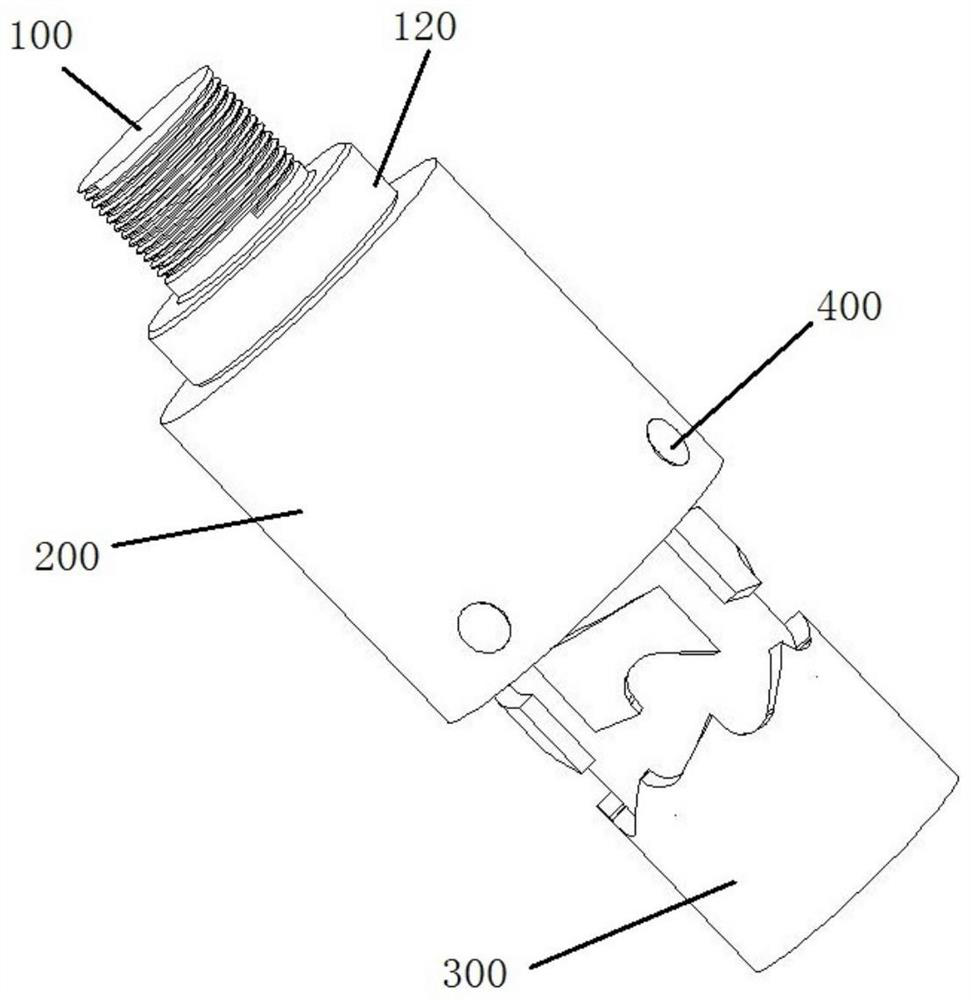
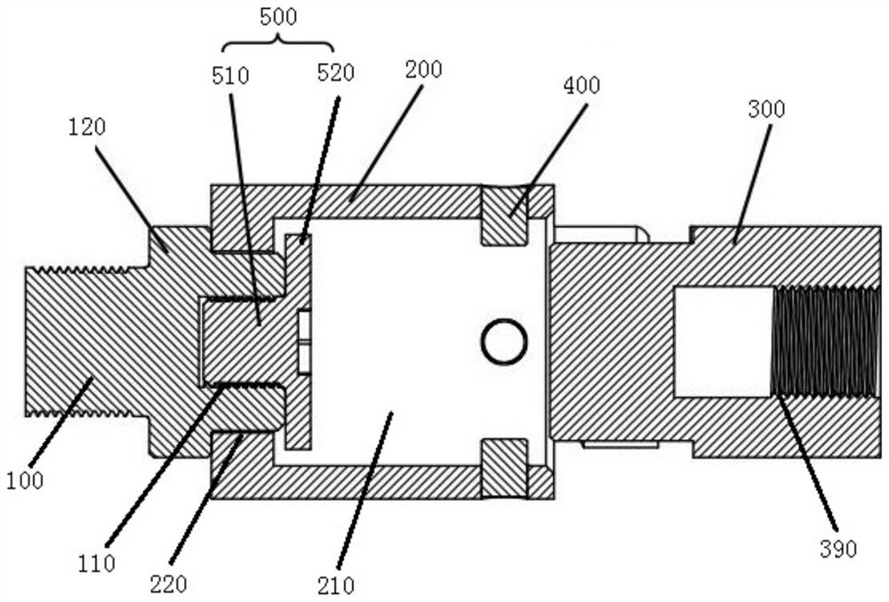
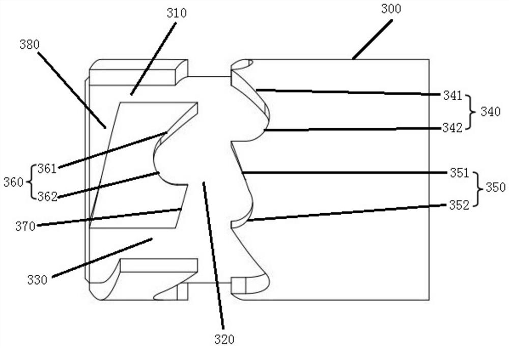
[0038] like Figure 1 to Figure 7 As shown, a single driving source push-pull compound ultra-high pressure coring device in a preferred embodiment of the present invention includes a connecting head 1, a movable head 2 and a fixed head 3, the connecting head 1 is used to connect with the active grasping part, and the fixed head 3 Used to connect with the grasped parts, the movable head 2 is rotatably set on the connecting head 1, and the movable head 2 is provided with at least two pins 4 evenly distributed in the circumferential direction, and the fixed head 3 is provided with the number and the pins The number of pins 4 is equal to the transmission unit, and each transmission unit is evenly spaced along the circumferential direction of the fixed head 3. The transmission unit includes an entry groove 310, a moving groove 320 and an exit groove 330 located on the side wall of the fixed head 3, and the entry groove 310 and the exit groove 330. The exit grooves 330 are arranged ...

Embodiment 2

[0047] This embodiment provides a method that can automatically grab and loosen, including:

[0048] The connecting head 100 is fixedly connected with the manipulator, and the movable head 200 is rotatably set on the connecting head 100. The movable head 200 has at least two pins 400 evenly spaced in the circumferential direction, and the fixed head 300 is connected to the grasped piece. The fixed head 300 has transmission units equal in number to the pins. The transmission unit includes an entry groove 310, a moving groove 320, and an exit groove 330 arranged on the outer wall of the fixed head 300. The entry groove 310 and the exit groove 330 are arranged at intervals and are self-fixing. One end of the head 300 extends along the axial direction of the fixed head 300. The moving groove 320 is located between the entering groove 310 and the moving groove 330 and communicates with the entering groove 310 and the exiting groove 330. The two side walls of the moving groove 320 ar...


PUM


Abstract

The invention relates to the technical field of grabbing mechanical devices, and discloses a single-driving-source push-pull composite ultrahigh-pressure coring device. The device is characterized in that a rotatable movable head is arranged on a connector in a sleeving mode, a pin is arranged on the movable head, a transmission unit is arranged on a fixed head connected with a grabbed piece, the transmission unit comprises an entering groove, a moving groove and an exiting groove which sequentially communicate, the two side walls of the moving groove are of staggered tooth-shaped structures, linear motion of an active grabbing piece connected through the connector can be converted into motion of the pin along the tooth-shaped structures, and automatic grabbing and loosening are achieved. According to the device, the automatic grabbing mechanism is simple in structure, small in size, capable of adapting to a small working space and free of an additional driving device, the whole mechanism is a pure mechanical mechanism, the automatic grabbing function can be achieved, reciprocating automatic grabbing and automatic loosening can be achieved, and influences of other factors are avoided. The invention further provides an automatic grabbing and loosening method, and the accuracy of mechanism movement judgment is improved.

Description

technical field [0001] The invention relates to the technical field of grasping mechanical devices, in particular to a push-pull composite ultra-high pressure coring device with a single driving source and a grasping and releasing method. Background technique [0002] In the field of automatic grasping control, in many mechanized productions, automatic grasping control has been widely used and has shown excellent performance. Automatic grasping control replaces manual repetitive operations, which greatly improves production efficiency and reduces labor production costs. However, in some narrow spaces, high temperature, and ultra-high pressure environment, manual operation is very dangerous. The general automatic grabbing control mechanism has a large structure, difficult pipeline laying, poor layout of the driving method, and components cannot withstand high temperatures. Due to factors such as high-pressure environment, these automatic grasping control mechanisms are diffi...

Claims


Application Information

Patent Timeline
IPC IPC(8): E21B25/00
CPCE21B25/00
Inventor 彭小波毛彦毫
Owner SHENZHEN UNIV
Why Eureka
Eureka Blog
Learn More