Rare earth permanent magnet motor driven centrifugal pump and self-lubricating method

A rare earth permanent magnet motor and centrifugal pump technology, applied in the field of centrifugal pumps, can solve the problems of large structure size, increased workload of bearings, and limited structure size applications that cannot meet the use requirements, and achieves the effect of compact axial structure

Active Publication Date: 2021-12-03
西安泵阀总厂有限公司
View PDF10 Cites 3 Cited by
  • Summary
  • Abstract
  • Description
  • Claims
  • Application Information

AI Technical Summary

Problems solved by technology

[0004] The embodiment of the present application provides a rare-earth permanent magnet motor-driven centrifugal pump and a self-lubricating method, which can solve the problem that the existing centrifugal pump and its driving parts have large structural dimensions, low safety and reliability, and cannot meet the requirements in applications with limited structural dimensions. The problem of use requirements, and the problem that the lubrication of the bearing will increase the extra workload

Method used


Image

  • Rare earth permanent magnet motor driven centrifugal pump and self-lubricating method
  • Rare earth permanent magnet motor driven centrifugal pump and self-lubricating method
  • Rare earth permanent magnet motor driven centrifugal pump and self-lubricating method

Examples


Embodiment Construction

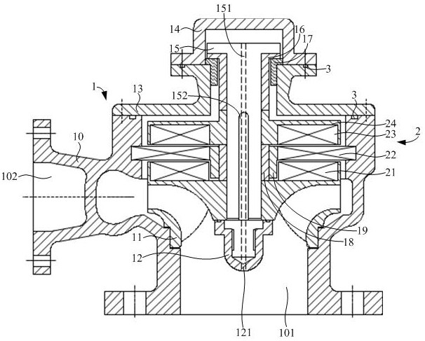
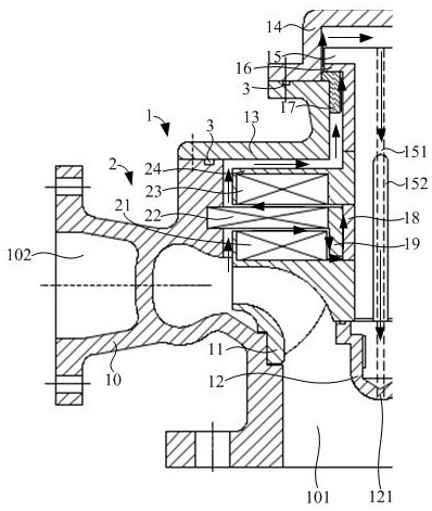
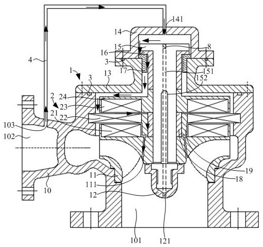
[0026] The following will clearly and completely describe the technical solutions in the embodiments of the present invention with reference to the accompanying drawings in the embodiments of the present invention. Obviously, the described embodiments are part of the embodiments of the present invention, not all of them. Based on the embodiments of the present invention, all other embodiments obtained by persons of ordinary skill in the art without making creative efforts belong to the protection scope of the present invention.

[0027] In the description of the embodiments of the present invention, it should be noted that the terms "center", "upper", "lower", "left", "right", "vertical", "horizontal", "inner", "outer " and other indicated orientations or positional relationships are based on the orientations or positional relationships shown in the drawings, and are only for the convenience of describing the embodiments of the present invention and simplifying the description,...


PUM


Abstract

The invention discloses a rare earth permanent magnet motor driven centrifugal pump and a self-lubricating method, and belongs to the field of centrifugal pumps. The centrifugal pump is sequentially sleeved with an upper shaft sleeve, an upper rotor and a lower shaft sleeve, then an impeller is fixed to the top end of a main shaft through an impeller nut, and an inward-concave mounting chamber is formed in the back face of the impeller; the outer portion of the upper shaft sleeve is sleeved with an upper bearing, and upper magnetic steel is clamped in a containing chamber on the upper rotor; the outer portion of the lower shaft sleeve is sleeved with a lower bearing; the lower bearing is firstly sleeved with a motor stator and then sleeved with lower magnetic steel in the axial direction of the lower bearing, and the lower magnetic steel is clamped in the mounting chamber; the main shaft, the upper / lower shaft sleeve, the upper / lower bearing, the upper rotor, the upper / lower magnetic steel, the motor stator, the impeller and the impeller nut are all located in a containing inner cavity formed by a pump body, a pump cover and an end cover; and a balance through hole is formed in the main shaft, a via hole is formed in the top end of the impeller nut, and the via hole and the balance through hole are coaxial so that an inlet of the pump body can communicate with the top end of the balance through hole. The structure of the rare earth permanent magnet motor driven centrifugal pump structure is light, and self-lubricating can be achieved.

Description

technical field [0001] The present application relates to the technical field of centrifugal pumps, in particular to a rare-earth permanent magnet motor-driven centrifugal pump and a self-lubricating method. Background technique [0002] The centrifugal pump works by using the rotation of the impeller to cause the centrifugal motion of the liquid medium. The basic structure of the centrifugal pump is composed of impeller, pump body, pump shaft, bearing, sealing ring, stuffing box and other parts. The existing centrifugal pump is driven by a motor. Specifically, the motor shaft of the motor is connected to the pump shaft of the centrifugal pump through a coupling and a bearing box, and the motor drives the centrifugal pump to work. [0003] Due to the use of auxiliary parts such as rolling bearings and mechanical seals, the existing centrifugal pumps and their driving mechanisms have large structural dimensions and low safety and reliability. They cannot meet the requirement...

Claims


Application Information

Patent Timeline
IPC IPC(8): F04D13/06F04D1/00F04D29/041F04D29/043F04D29/046F04D29/06F04D29/42F04D29/58F04D29/62
CPCF04D13/0606F04D13/0633F04D13/0646F04D1/00F04D29/046F04D29/061F04D29/586F04D29/041F04D29/043F04D29/426F04D29/628
Inventor 魏清希高丙文王辉程蕾
Owner 西安泵阀总厂有限公司
Why Eureka
Try Eureka