Backward centrifugal impeller and backward centrifugal ventilator comprising same

A centrifugal impeller and rear disc technology, which is applied in mechanical equipment, radial flow pumps, machines/engines, etc., can solve the problems of reduced flow at the impeller outlet, improve reliability and life, improve outlet flow and aerodynamic efficiency, and improve The effect of effort

Pending Publication Date: 2021-12-03
浙江科贸实业有限公司
View PDF0 Cites 0 Cited by
  • Summary
  • Abstract
  • Description
  • Claims
  • Application Information

AI Technical Summary

Problems solved by technology

The existence of internal leakage leads to a decrease in the outlet flow of the impeller and a part of useless work, that is, the formation of internal leakage loss

Method used


Image

  • Backward centrifugal impeller and backward centrifugal ventilator comprising same
  • Backward centrifugal impeller and backward centrifugal ventilator comprising same
  • Backward centrifugal impeller and backward centrifugal ventilator comprising same

Examples


Embodiment 1

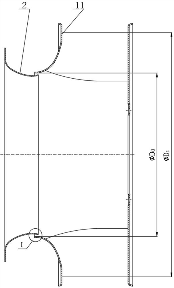
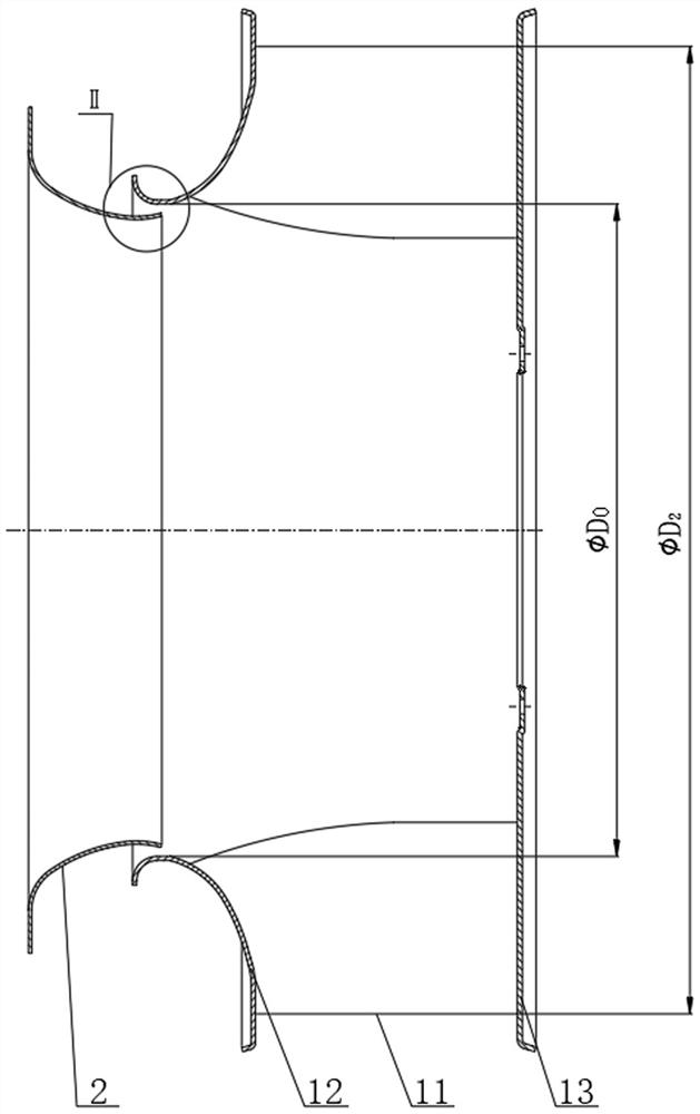
[0023] see Figure 3-Figure 5 , the present embodiment proposes a backward centrifugal impeller, including a rear disk 13, a front disk 12, and a plurality of blades 11 arranged between the rear disk 13 and the front disk 12. The front end of the inner ring of the front disk 12 is provided with an arc-shaped Lan Duan.

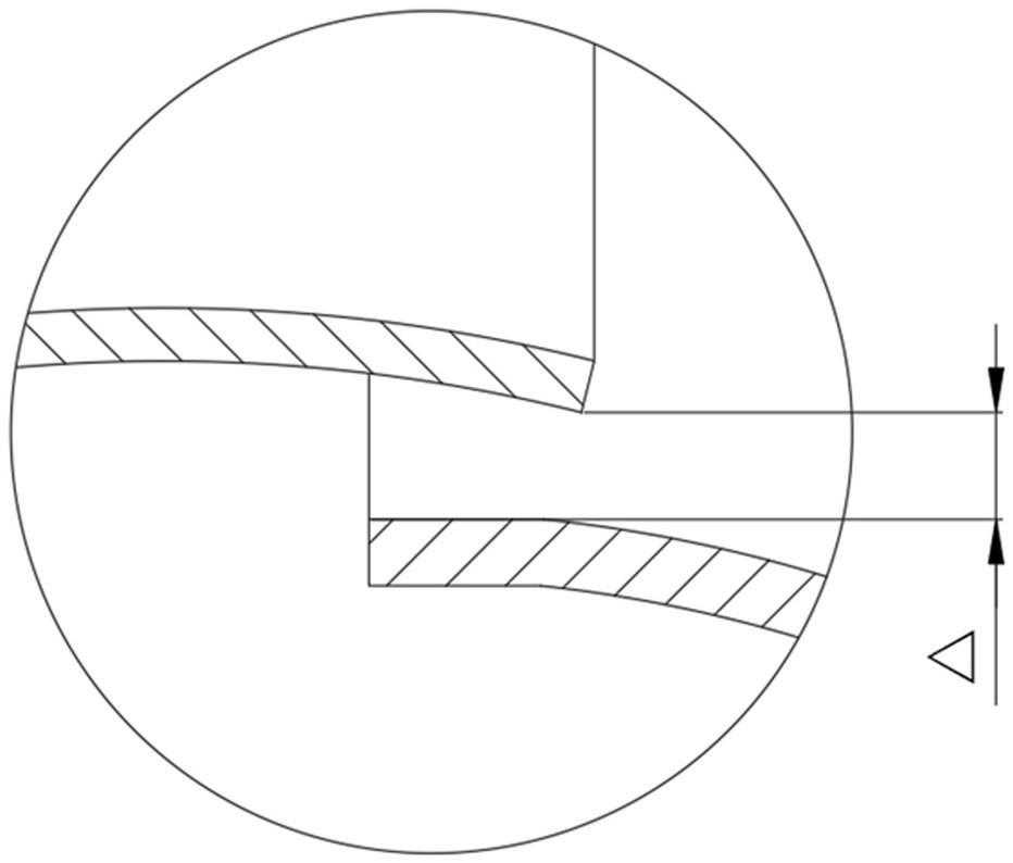
[0024] Specifically, the arc-shaped flange section in this embodiment includes a flange plane section ab, an arc-shaped constriction section bc, and a straight cylinder section cd. The flange plane section ab is an annular plane perpendicular to the axis of the impeller, and the straight cylinder section cd is The centerline coincides with the axis of the impeller in the shape of a cylinder, the arc-shaped contraction section bc has an arc-shaped cross-section along the axial direction, and its convex surface is inward, and the cross-sectional shape is arc-shaped, elliptical or other curved shapes. In this embodiment The circular arc shape is preferably used i...

Embodiment 2

[0027] This embodiment proposes a backward centrifugal impeller, including a rear disc 13, a front disc 12 and a number of blades 11 arranged between the rear disc 13 and the front disc 12, and the front end of the inner ring of the front disc 12 is provided with an arc-shaped flange part.

[0028] Specifically, the arc-shaped flange section in this embodiment includes a flange plane section ab, an arc-shaped constriction section bc, and a straight cylinder section cd. The flange plane section ab is an annular plane perpendicular to the axis of the impeller, and the straight cylinder section cd It is in the shape of a cylinder whose center line coincides with the axis of the impeller. The arc-shaped constriction section bc has an arc-shaped cross-section along the axial direction, and its convex surface is inward. The cross-sectional shape is arc-shaped. The backward centrifugal impeller in this application is applied On the centrifugal fan, when assembling, the outlet end of ...


PUM


Abstract

The invention discloses a backward centrifugal impeller and a backward centrifugal ventilator comprising the same. The ventilator comprises the impeller and an air inlet, the impeller comprises a rear disc, a front disc and a plurality of blades arranged between the rear disc and the front disc, an arc-shaped flange section is arranged at the front end of the front disc, and the air inlet is inserted into the front disc of the impeller to form looping fit. The structure is improved according to the looping fit relation of the impeller and the air inlet of the backward centrifugal ventilator, the arc-shaped flange section is additionally arranged at the position of the inner ring of the front disc of the impeller so as to reduce inner leakage loss and improve the impeller outlet flow and aerodynamic efficiency, the output of the impeller is improved, energy is saved, and consumption is reduced. Meanwhile, the rigidity of an impeller inlet ring is increased, the operation reliability of the impeller inlet ring is improved, the overall dimension of the whole ventilator is not increased while the arc-shaped flange section is additionally arranged, and positive significance is achieved.

Description

technical field [0001] This patent relates to the technical field of ventilators, in particular to a rearward centrifugal impeller with an additional flange section at the inlet of the front disc and a rearward centrifugal fan. Background technique [0002] The impeller is the main part of the centrifugal fan, mostly a closed impeller, mainly including the rear disc, the front disc and some blades arranged in between. Usually, between the impeller of the backward centrifugal fan and the air inlet, a part of the outlet end of the air inlet is inserted into the impeller, such as figure 1 , figure 2 shown. When the impeller and the air inlet of the backward centrifugal fan are fitted with sleeves, because the impeller is a part that rotates around the drive shaft, and the air inlet is a static guide part, there must be a radial gap between the two, that is, the front disc of the impeller. The inner diameter of the inlet is larger than the outer diameter of the outlet of the...

Claims


Application Information

Patent Timeline
Patent Type & Authority Applications(China)
IPC IPC(8): F04D29/28F04D29/30F04D29/66F04D29/16F04D17/16F04D29/42
CPCF04D29/281F04D29/30F04D29/667F04D29/666F04D29/162F04D17/16F04D29/4213
Inventor 裘鑫徐天赐
Owner 浙江科贸实业有限公司
Why Eureka
Try Eureka