Protective municipal pipeline laying device with pressure relief structure

A technology for municipal pipelines and pressure relief structures, applied in pipeline laying and maintenance, mechanical equipment, pipes/pipe joints/fittings, etc., can solve problems such as easy breakage, inability to support cement pipes, and lack of pressure relief effects , to achieve the effect of improving the practicality

Active Publication Date: 2021-12-03
广东智铭设计有限公司
View PDF6 Cites 0 Cited by
  • Summary
  • Abstract
  • Description
  • Claims
  • Application Information

AI Technical Summary

Problems solved by technology

[0006] The purpose of the present invention is to provide a protective municipal pipeline laying device with a pressure relief structure, so as to solve the problem of simply supporting the cement pipeline in contact with the above-mentioned background technology. It is very easy to be damaged, and it does not have a good pressure relief effect, which leads to the inability of the lowered bearing capacity to support the cement pipeline stably, and cannot stably guide the contacting pipe fittings, requiring the user Manually push it to the corresponding position, and it is prone to breakage during the movement

Method used


Image

  • Protective municipal pipeline laying device with pressure relief structure
  • Protective municipal pipeline laying device with pressure relief structure
  • Protective municipal pipeline laying device with pressure relief structure

Examples


Embodiment Construction

[0028] The following will clearly and completely describe the technical solutions in the embodiments of the present invention with reference to the accompanying drawings in the embodiments of the present invention. Obviously, the described embodiments are only some, not all, embodiments of the present invention. Based on the embodiments of the present invention, all other embodiments obtained by persons of ordinary skill in the art without making creative efforts belong to the protection scope of the present invention.

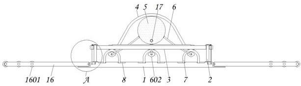
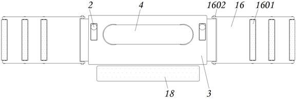
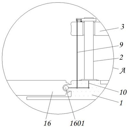
[0029] see Figure 1-7 , the present invention provides a technical solution: a protective municipal pipeline laying device with a pressure relief structure, including a base 1, a nest 2, a movable support seat 3, a protective layer 4, a first air bag 5, a first supply Air hose 6, adhesive layer 601, second air bag 602, conflicting member 7, guide groove 8, first drawstring 9, second drawstring 10, movable rack 11, accommodating groove 12, return spring 13, pu...


PUM


Abstract

The invention discloses a protective municipal pipeline laying device with a pressure relief structure. The protective municipal pipeline laying device with the pressure relief structure comprises a base, an embedded part, a movable supporting seat, a containing groove and a buffer air cushion, wherein the embedded part is fixedly connected to the upper end of the base; the movable supporting seat is installed at the outer end of the embedded part in an embedded mode; a protective layer is connected to the upper end of the movable supporting seat in an adhesive mode; the inner end of the protective layer is connected with a first air bag in an adhesive mode; and a first air supply hose is installed at the outer end of the first air bag in a penetrating mode. According to the protective municipal pipeline laying device with the pressure relief structure, a cement pipe fitting is lowered to the upper end of the movable supporting seat, and the spherical first air bag on the surface is stressed in advance and deforms, so that the supporting area is enlarged to preliminarily support the cement pipe fitting; and meanwhile, a second air bag communicated with the spherical first air bag expands accordingly, and the cement pipe fitting is subjected to secondary supporting work in cooperation with rubber abutting pieces pressed to deform for supporting, so that pressure relief supporting work is further conducted on the pressure generated when the cement pipe fitting is put down.

Description

technical field [0001] The invention relates to the technical field of pipeline laying, in particular to a protective municipal pipeline laying device with a pressure relief structure. Background technique [0002] With the continuous increase of construction, the demand for work such as pipeline laying is also increasing. In the process of cement pipelines going down along the unloading truck, corresponding buffer devices need to be adapted for support, otherwise pipeline breakage will easily occur. However, there are still certain defects in the existing lowering buffer device for pipeline laying, such as: [0003] 1. The existing lowering buffer device for pipeline laying can only simply support the cement pipeline in contact. During the process of unloading and lowering, it is easy to be damaged due to excessive gravity, and it does not have a good pressure relief effect. , leading to the inability of the decentralized bearing capacity to support the cement pipeline sta...

Claims


Application Information

Patent Timeline
Patent Type & Authority Applications(China)
IPC IPC(8): F16L1/028F16L1/06F16L1/11
CPCF16L1/028F16L1/06F16L1/11
Inventor 李雪
Owner 广东智铭设计有限公司
Why Eureka
Try Eureka