
Experimental device for friction loss between contact wire and pantograph of high-strength high-speed rail

A technology of contact wire and friction loss, which is applied in the field of experimental equipment for friction loss between high-strength high-speed iron contact wire and pantograph, can solve the problems of pantograph constraints, etc. The effect of promotion

Active Publication Date: 2022-07-26
JIANGSU MEILIN COPPER
View PDF6 Cites 0 Cited by
  • Summary
  • Abstract
  • Description
  • Claims
  • Application Information

AI Technical Summary

Problems solved by technology

[0003] Aiming at the wear and tear problem of pantograph components, there are various online high-definition camera detection components, and there is also an effective method for detecting wear by using cross-sectional resistance and current methods disclosed in CN 108981556 B. However, these detection They are all based on pantographs that have been used for a long time. When researching the wear of contact wires and pantographs in the laboratory, it is necessary to collect the pantographs used for external installation, and to study the new structure and materials of pantographs. R&D poses significant constraints and requires an experimental setup that facilitates laboratory-based sampling studies of friction losses between the high-speed rail contact wire and the pantograph

Method used


Image

  • Experimental device for friction loss between contact wire and pantograph of high-strength high-speed rail
  • Experimental device for friction loss between contact wire and pantograph of high-strength high-speed rail
  • Experimental device for friction loss between contact wire and pantograph of high-strength high-speed rail

Examples


Embodiment 1

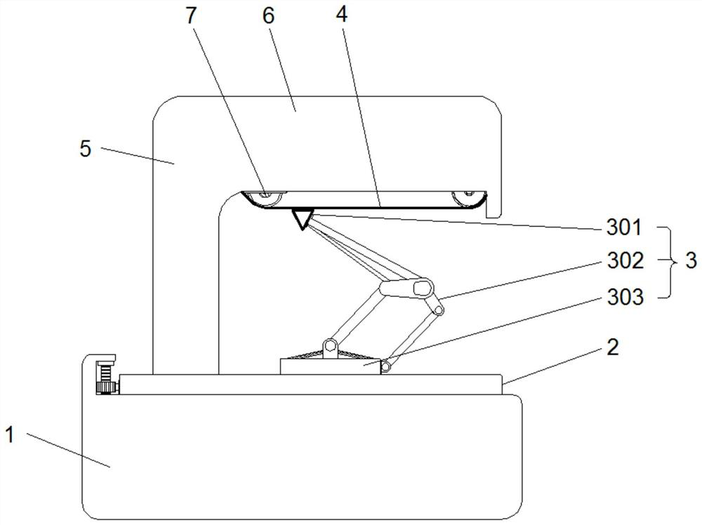
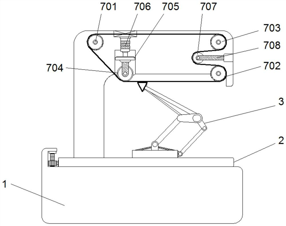
[0030] see Figures 1 to 4, in the embodiment of the present invention, the experimental device for friction loss between the high-strength high-speed rail contact wire and the pantograph includes a base 1, and the upper end of the base 1 is provided with a test platform 2 for placing the pantograph assembly 3, The base 303 of the pantograph assembly 3 is fixedly clamped on the upper end surface of the experimental platform 2, the sliding plate 301 of the pantograph assembly 3 is fixed on the upper end of the base 303 through the support arm 302, and the upper end of the sliding plate 301 is in contact with the experimental lead 4, The experimental lead 4 is installed on the wire guide assembly 7 opposite to the pantograph assembly 3 in the rotation transmission direction, the wire guide assembly 7 is installed in the top plate 6 on the base 1, and the top plate 6 is fixed by the stand 5 Set on the base 1, the experimental lead 4 rotates at a high speed under the drive of the ...

Embodiment 2

[0039] see Figures 5 to 7 , on the basis of Example 1, the embodiment of the present invention further improves the experimental device for the friction loss between the high-strength high-speed rail contact wire and the pantograph to simulate the travel of the high-speed rail during operation, so that the pantograph assembly 3 is subjected to simulated travel. The bumps and vibrations on the route are as follows:

[0040] The machine base 1 is also provided with a bumpy vibration assembly that acts synchronously with the wire guide assembly 7 and simulates bumps and vibrations encountered by the high-speed rail. The pantograph assembly 3 is fixedly clamped on the end surface of the movable plate 203, the lower end of the movable plate 203 is provided with a contact plate 204 made of elastic material, and a push box 23 is arranged under the contact plate 204, and the push box 23 can be lifted and lowered. Below the contact plate 204, the push box 23 is spaced apart from the ...

Embodiment 3

[0045] On the basis of Example 1, the embodiment of the present invention upgrades the function of the experimental device for friction loss between the high-strength high-speed rail contact wire and the pantograph, specifically:

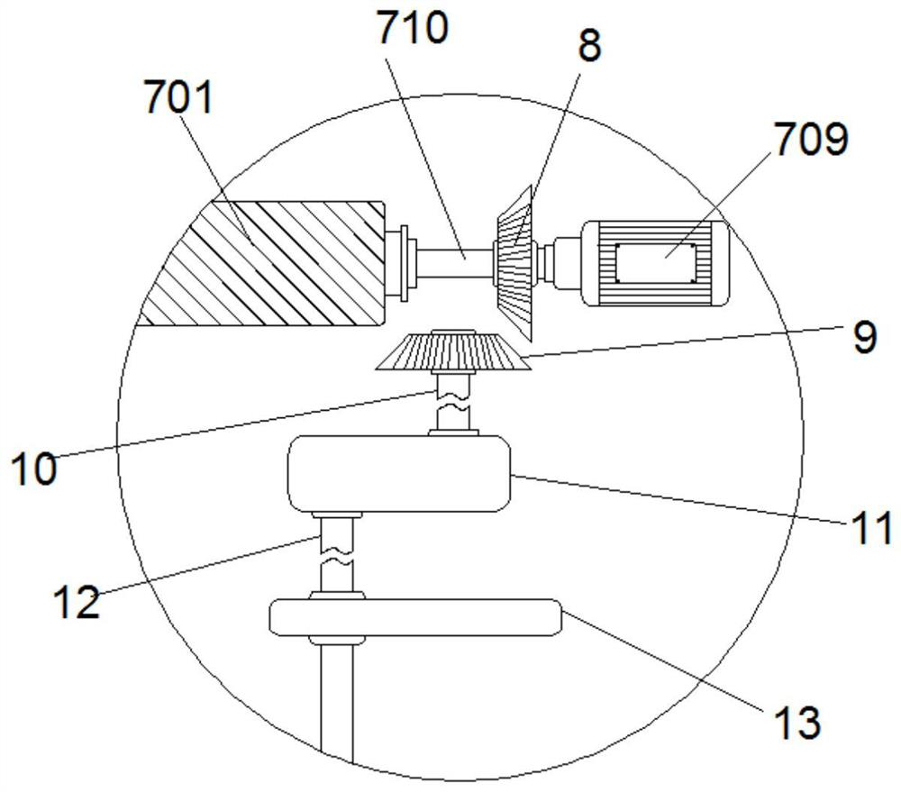
[0046] The first rotating shaft 710 in the wire guide assembly 7 is also installed with a data acquisition device, and the data acquisition device is a rotational speed detector, a mileage detector, a timer, etc. , to obtain the friction speed and total mileage of the pantograph assembly 3 and the experimental lead 4, so as to provide necessary data parameters for the subsequent friction loss experiments and ensure the accurate development of the experiments.


PUM


Abstract

The invention discloses an experimental device for friction loss between a contact wire of a high-strength high-speed rail and a pantograph. On the wire conducting assembly opposite to the pantograph assembly, the base is provided with a lateral swinging assembly that acts synchronously with the conducting wire assembly and simulates left and right swinging when the high-speed rail travels. , Simulate the bumpy vibration components that high-speed rail encounters bumps and vibrations, and use the wire conduction components to achieve high-speed transmission of experimental wires in a closed loop. Within a limited operating range, quickly and efficiently form the required friction loss experimental research samples, using lateral swing components. And the bumpy vibration component simulates the swing and bumpy vibration of the high-speed rail car during driving, improves the wear degree of the pantograph component and the experimental wire, and facilitates the friction loss experiment between the high-strength high-speed rail contact wire and the pantograph.

Description

technical field [0001] The invention relates to the field of experimental devices, in particular to an experimental device for friction loss between a high-strength high-speed rail contact wire and a pantograph. Background technique [0002] The pantograph is an electrical device for electric traction locomotives to obtain electrical energy from the catenary. It is installed on the roof of the electric traction locomotive. As a high-speed train, the high-speed rail is driven by electricity. Mechanical energy is an efficient and reliable power source for high-speed railways. Therefore, the carriages of high-speed railways are also equipped with pantograph components. The pantograph components generally use telescopic brackets to support the sliding plate at the upper end to contact the electrical contact line. The pantograph components are especially It is often inevitable to wear the skateboard as a contact part, especially when it is installed on a high-speed rail car with ...

Claims


Application Information

Patent Timeline
Patent Type & Authority Patents(China)
IPC IPC(8): G01N19/02
CPCG01N19/02
Inventor 李小武翟金勇邵云林
Owner JIANGSU MEILIN COPPER
Learn More