Cable fault detection method based on red and ultraviolet composite imaging

A cable fault and composite imaging technology, which is applied in image enhancement, image analysis, image data processing, etc., can solve problems such as large deviations

Pending Publication Date: 2021-12-03
FUJIAN UNIV OF TECH
View PDF5 Cites 0 Cited by
  • Summary
  • Abstract
  • Description
  • Claims
  • Application Information

AI Technical Summary

Problems solved by technology

However, when the infrared detection of electrical equipment is carried out on site, it is often affected by on-site factors, such as solar radiation, which makes the position of the measured fault point deviate from the actual fault point position.

Method used


Image

  • Cable fault detection method based on red and ultraviolet composite imaging
  • Cable fault detection method based on red and ultraviolet composite imaging
  • Cable fault detection method based on red and ultraviolet composite imaging

Examples


Embodiment Construction

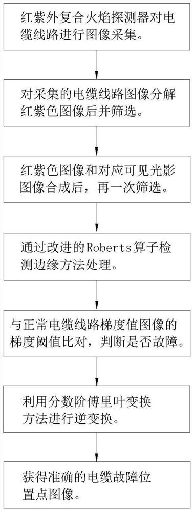
[0028] see figure 1 , a kind of cable fault detection method based on red-ultraviolet compound imaging in the embodiment, it comprises the following steps:

[0029] S1: A number of red-ultraviolet composite flame detectors evenly distributed on the cable line section to be tested collect images of the cable line, obtain a number of cable line images, and decompose them into red-purple images and visible light and shadow images;

[0030] S2: Screening the red-purple image, and selecting the red-purple image of the bright red-purple cable line;

[0031] S3: Using the image feature point matching method to synthesize the red-purple image of the cable line and the corresponding visible light and shadow image, further screening the red-purple bright and obvious cable line image, and obtaining the suspected faulty cable line image;

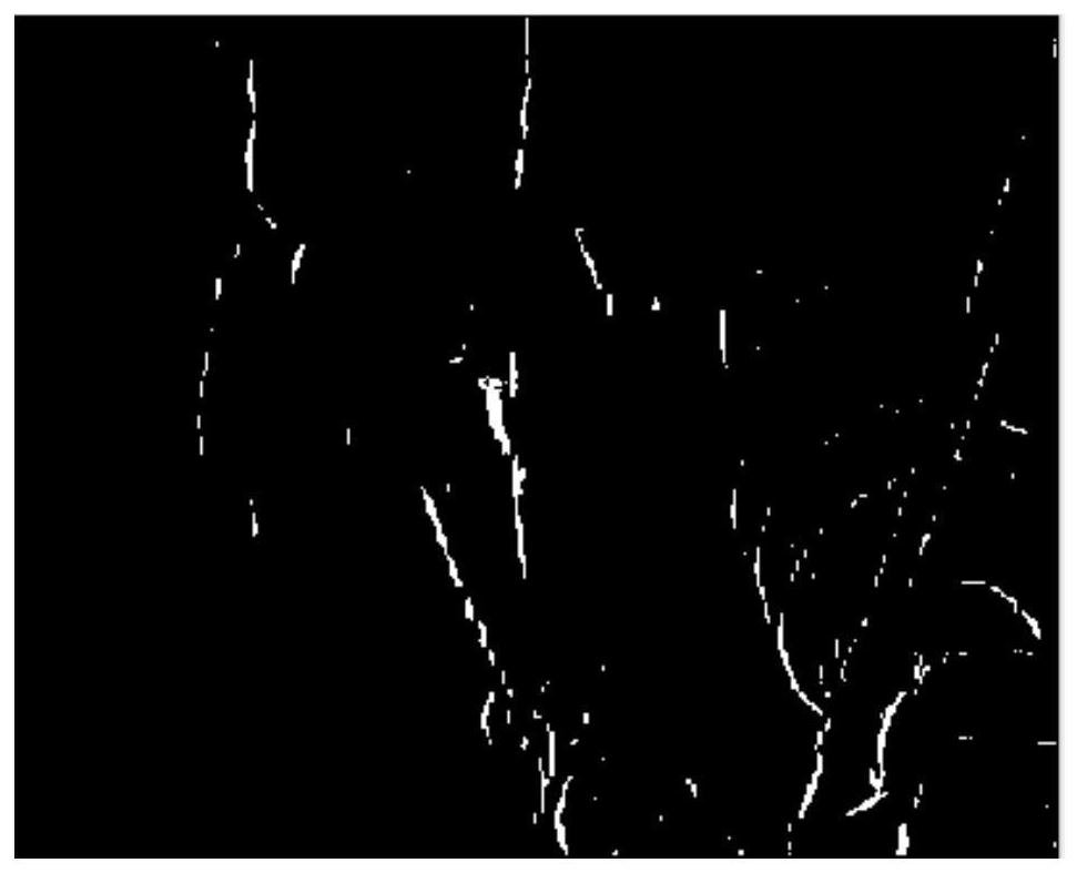
[0032] S4: Process the suspected faulty cable line image through an improved Roberts operator detection edge method to obtain a suspected faulty cable...


PUM


Abstract

The invention relates to a cable fault detection method based on red and ultraviolet composite imaging. The method comprises the steps of carrying out the image collection of a cable line through a red and ultraviolet composite flame detector, decomposing an image into a red and purple image and a visible light and shadow image, screening the red and purple image, synthesizing the red and purple image and the visible light and shadow image, carrying out the screening again, and obtaining a suspected fault cable line image; carrying out noise reduction and graying processing through an improved Roberts operator, and carrying out fractional order Fourier transform processing in Matlab to obtain an accurate cable fault position point image. By adopting the above technical scheme, image acquisition is prevented from being affected by field factors such as sunlight radiation, the fault point position is determined more accurately, and the cable line fault identification and detection can be carried out in various underground environments and environments in which people are not easy to reach.

Description

technical field [0001] The invention relates to the technical field of cable detection, in particular to a cable fault detection method based on red-ultraviolet composite imaging. Background technique [0002] At present, infrared thermal imaging technology and visible light imaging technology are increasingly widely used in my country's power system, and have become a necessary means to carry out status inspection of electrical equipment. However, when the infrared detection of electrical equipment is carried out on site, it is often affected by on-site factors, such as solar radiation, which causes a large deviation between the measured fault point location and the actual fault point location. Contents of the invention [0003] Aiming at the deficiencies of the existing technology, the present invention provides a more accurate determination of the location of the fault point, which satisfies various underground environments and environments where personnel are not easil...

Claims


Application Information

Patent Timeline
Patent Type & Authority Applications(China)
IPC IPC(8): G06T7/00G06T5/00G06T5/50
CPCG06T7/0004G06T5/50G06T5/002G06T2207/10048
Inventor 黄旭红赵楠汤声平郑上
Owner FUJIAN UNIV OF TECH
Why Eureka
Try Eureka